Disclaimer
This information HAS errors and is made available WITHOUT ANY WARRANTY OF ANY KIND and without even the implied warranty of MERCHANTABILITY or FITNESS FOR A PARTICULAR PURPOSE. It is not permissible to be read by anyone who has ever met a lawyer or attorney. Use is confined to Engineers with more than 370 course hours of engineering.
If you see an error contact:
+1(785) 841 3089
inform@xtronics.com
Electronic Formulas

Power
- W = Watt
- J = Joule
- S = Second
,

Transformer inductance and coupling
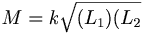
Where:
- M = Mutual inductance in Henrys
- k = coefficient of coupling
- L_1 Inductance of first winding
- L_2 Inductance of second winding
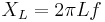
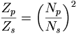
Turns ratio
For Iron Core ,
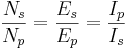
Where:
- p subscript refers to Primary winding
- s subscript refers to secondary winding
- N = number of turns
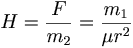
Ohms law in magnetics
Where:
- F = repulsive force
- r = distance between poles
- μ permeability ( μ of air = 1)
- H = Magnetizing Force in Oersted
- mmf = Magnetic Motive Force - in Gilberts
- Orested = Gilberts/CM
- β = Flux density in Gauss
- φ = Total flux density in Maxwells
- r = Reluctance
- P = Permeance

mmf = φR

,
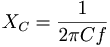
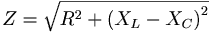
Impedance
Where
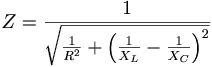
- XL refers to inductive reactance
- XC refers to capacitive reactance
Impedance through a transformer
Series RCL
Parallel RCL
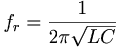
Parallel LC Resonance
Q or Quality factor

Time constance
Τ = time in seconds to 2/3 rise
Τ = RC

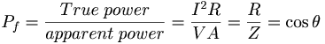
Power factor
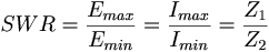
Standing Wave Ratio (SWR)
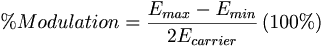
Modulation
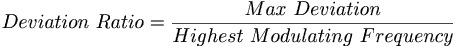 Deviation = modulating index Deviation ratio =
Deviation / highest modulating frequency
Deviation = modulating index Deviation ratio =
Deviation / highest modulating frequency
Transistors
- Ic = Ibβ
or
-

β = beta </math> Ib = Base current Ic = Collector current
- Transconductance
- Transconductance is a contraction of transfer conductance. The old unit of conductance, the mho (ohm spelled backwards), was
replaced by the SI unit, the siemens, with the symbol S (1 siemens = 1 ampere per volt).
-
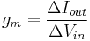
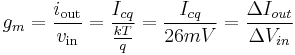
For small signal alternating current, the Transconductance is estimated:
-
Where :
- gm = small signal transconductance
-
 Thermal voltage
- k Boltzmann constant ,
- Icq = quiescent point, Q-point, or bias point
Distortion begins somewhere once the base voltage exceeds about 5 to 15mVp-p
If we look at large signals we must use
-

Where :
- Gm = Large signal Transconductance (not to be confused with gm
- Small-signal-input-resistance ( Rπ )for a common emitter amp with the emitter AC grounded:
-
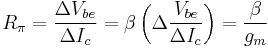
Which means that input resistance goes up with β
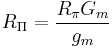
- Large-signal-Input-resistance ( RΠ )for a common emitter amp with the emitter AC grounded:
-
Ebers-Moll equation
-
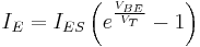
-
 (approximately 26 mV at 300 K ≈ room temperature).
where
- VT is the Boltzmann constant kT / q
- q Electronic Charge
- TTemperature in K
- IE is the emitter current
- IC is the collector current
- αF is the common base forward short circuit current gain (0.98 to 0.998)
- IES is the reverse saturation current of the base–emitter diode (on the order of 10−15
to 10−12 amperes)
- VBE is the base–emitter voltage
ESR formulas
Email