This information HAS errors and is made available WITHOUT ANY WARRANTY OF ANY KIND and without even the implied warranty of MERCHANTABILITY or FITNESS FOR A PARTICULAR PURPOSE. It is not permissible to be read by anyone who has ever met a lawyer or attorney. Use is confined to Engineers with more than 370 course hours of engineering.
If you see an error contact:
+1(785) 841 3089
inform@xtronics.com
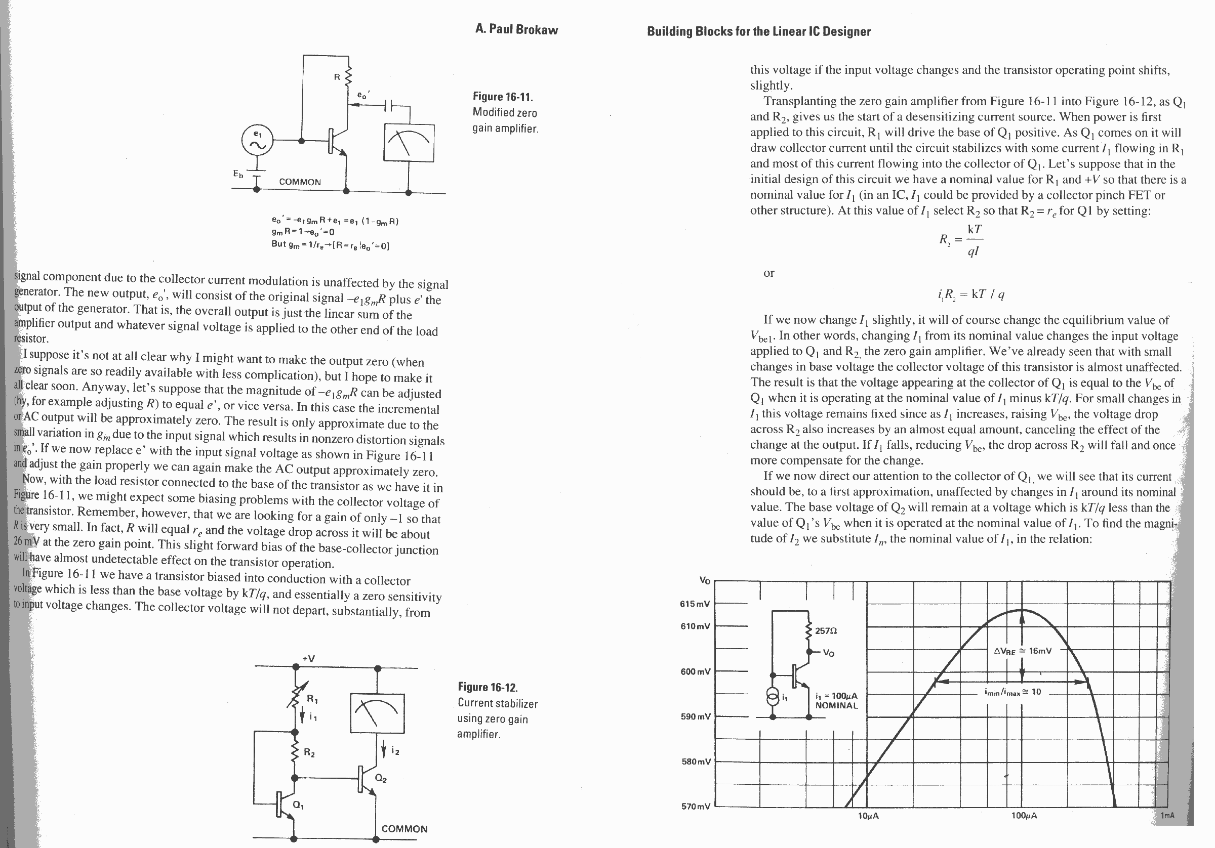
The reason is to help keep things constant as the voltage supply varies and to enable high yields in spite of batch-to-batch differences in IC manufacturing. Inside most ICs there are bias circuits that use zero-gain circuits to set a bias current that is stable with different voltage supplies.
The best source of information I found on this is from A. Pail Brokaw where he writes in
Analog Circuit Design, First Edition : Art, Science and Personalities (EDN Series for Design Engineers)
(Edited by non other than Jim Williams).

Zero Gain Amp
The two key sentences: 1 - "R will equal Re and the voltage drop across it will be about 26mV at the zero gain point."
This value comes from Thermal voltage Vt = kT/q ≈ 26 mv Where k = Boltzmann's Constant, q = Electronic Charge, and T = temp in K
2- "... the voltage appearing at the collector of Q1 is equal to the Vbe of Q when it is operating at the nominal value of I1 minus kT/q."
kT/q varies with temperature, but in my case it doesn't matter because both samples go through the same diode - thus the same temperature.
The Vec should be quite constant in my application even with slight current changes and the circuit is quit simple - changing a diode to a transistor of the same cost and adding a resistor.
I'm getting about 50 ohms for a 2N3904 with current at 1mA
| Top Page | wiki Index |
(C) Copyright 1994-2019
All trademarks are the property of their respective owners.