
This information HAS errors and is made available WITHOUT ANY WARRANTY OF ANY KIND and without even the implied warranty of MERCHANTABILITY or FITNESS FOR A PARTICULAR PURPOSE. It is not permissible to be read by anyone who has ever met a lawyer or attorney. Use is confined to Engineers with more than 370 course hours of engineering.
If you see an error contact:
+1(785) 841 3089
inform@xtronics.com
The ESR rating of a capacitor is a rating of quality. A theoretically perfect capacitor would be lossless and have an ESR of zero. It would have no in-phase AC resistance. We live in the real world and all capacitors have some amount of ESR
To understand why, let us review what a capacitor is, what they are made of, and how we rate them.
A capacitor consists of two conductive metal plates separated by an insulating dielectric. The dielectric can be made of glass, ceramic, tantalum oxide, or plastics such as polyethylene or polycarbonate. Even air can be used as the dielectric. When the capacitor holds some energy in the form of extra electrons on one plate and electron holes on the other, we say that the capacitor is charged.
Capacitance (C) is the amount of charge per volt of potential that a capacitor holds.
C = Q / V
Capacitance is measured in Farads, but most often a small fraction of a Farad thus:
The energy stored in a capacitor is E = CV2/2 (E is in joules).
Thus, the average power in watts is Pav = CV2 / 2t
where t is the time in seconds.
Thus -capacitance of a capacitor (C) is related to
Here A and d are based on meters as the unit and ε is in Farads per meter (or Coulombs squared per newton-meters squared). Notice the force unit involved—it explains why capacitor microphonics (remember the good old condenser microphone?) and a mechanical failure mode of capacitors).
Dielectric constant (k) gets its value by comparison of the charge holding ability of a vacuum, where k = 1.
Thus, k is the ratio of the capacitance with a volume of dielectric compared to that of a vacuum dielectric.

Dielectric constants vary with temperature, voltage, and frequency
making capacitors messy devices to characterize. Whole books have been
written about choosing the correct dielectric for an application,
balancing the desires of temperature range, Temperature stability, size,
cost, reliability, dielectric absorption, voltage coefficients, current
handling capacity (ESR).
See the Secrets of capacitor codes page for more information
Dielectric strength is a property of the dielectric that is usually expressed in volts per mil (V/.001") or volts per centimeter (V/cm). It is the maximum potential difference across a unit thickness of the dielectric before it breaks down and allows a spark. If we exceed the dielectric strength, an electric arc will "flash over" and often weld the plates of a capacitor together.
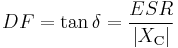
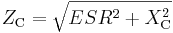
The Q of a capacitor is important in tuned circuits because they are more damped and have a broader tuning point as the Q goes down.

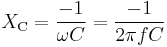
where XC is the capacitive reactance
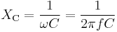
and R is the soon-to-be-defined term of ESR. Q is inversely proportional to the amount of energy dissipated in the capacitor.
Thus, ESR rating of a capacitor is inversely related to its quality.
The inverse of Q is the dissipation factor (tan(δ)). Thus, tan(δ) = ESR/XC and the higher the ESR the more losses in the capacitor and the more power we dissipate. If too much energy is dissipated in the capacitor, it heats up to the point that values change (causing drift in operation) or failure of the capacitor.
The ripple current is sometimes rated for a capacitor in RMS current. Remembering that P = I2R where R in this case is ESR it is plain to see that this is a power dissipation rating.
This is the phenomenon where after a capacitor has been charged for some time, and then discharged, some stored charge will migrate out of the dielectric over time, thus changing the voltage value of the capacitor. This is extremely important in sample and hold circuit applications. The typical method of observing Dielectric Absorption is to charge up a cap to some known DC voltage for a given time, then discharge the capacitor through a 2 ohm resistor for one second, then watch the voltage on a high-input-impedance voltmeter. The ratio of recovered voltage (expressed in percent) is the usual term for Dielectric absorption. The charge absorption effect is caused by a trapped space charge in the dielectric and is dependent on the geometry and leakage of the dielectric material.
ESL (Equivalent Series Inductance) is pretty much caused by the inductance of the electrodes and leads. The ESL of a capacitor sets the limiting factor of how well (or fast) a capacitor can de-couple noise off a power bus. The ESL of a capacitor also sets the resonate-point of a capacitor. Because the inductance appears in series with the capacitor, they form a tank circuit.
ESR is the sum of in-phase AC resistance. It includes resistance of the dielectric, plate material, electrolytic solution, and terminal leads at a particular frequency.
ESR acts like a resistor in series with a capacitor (thus the name Equivalent Series Resistance). This resistance often is the cause of failures in capacitor circuits.
These circuits look just fine on paper, but the hidden resistance causes failure due to heat buildup. To charge the dielectric material current needs to flow down the leads, through the lead plate junction, through the plates themselves - and even through the dielectric material.
Dielectric losses can be thought of as friction of aligning dipoles and appears as an increase (reduction of the rate of decrease) of the measured ESR as frequency increases. This increase is what makes the resistance vs freq line go flat above a certain frequency.
As the dielectric thickness increases so does the ESR. As the plate area increases, the ESR will go down if the plate thickness remains the same. To test a capacitor's ESR requires something other than a standard capacitor meter. While a capacitor value meter is a handy device, it will not detect capacitor failure modes that raise the ESR. As the years go by, more and more designs rely on low ESR capacitors to function properly. ESR-failed caps can present circuit symptoms that are difficult to diagnose.
Where:
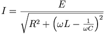
Reactance is used to compute amplitude and phase changes of sinusoidal current. It is denoted by the symbol ,
 and can be used in place of resistance in many calculations - It can be
thought of as the effective AC resistance at some frequency.
,
and can be used in place of resistance in many calculations - It can be
thought of as the effective AC resistance at some frequency.
,
The -1 above is because the reactance is negative from the following vector math: Both reactance ,
and resistance ,
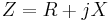
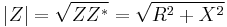
 are required to calculate impedance ,
 .
.
In some circuits one of these may dominate, but an approximate knowledge of the minor component is useful to determine if it may be neglected.
 where :j2 = − 1
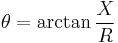
The 'magnitude' ,
 phase ,
 of the impedance depend on the combined action of the resistance and the reactance. ,
is the ratio of the voltage and current amplitudes, while the ,
is the voltage–current phase difference.
of the impedance depend on the combined action of the resistance and the reactance. ,
is the ratio of the voltage and current amplitudes, while the ,
is the voltage–current phase difference.
 where Z * is the complex conjugate of Z
 the reactance is inductive
 then the impedance is purely resistive
 the reactance is capacitive The reciprocal of reactance ( 1 / X) is susceptance - not a term you will likely meet up with.
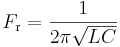
XL = ωL = 2πfL Relationship between angular frequency ω and frequency f
Where
 ; dimensionless)
 ,
,

 is the permittivity of the dielectric
 is the permittivity of free space =(,
 )
)
 ,
,

Where energy E (in joules) stored in a capacitor is given by

Thus, the average power in watts where t = time in seconds.
 ,
,
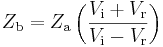
Characteristic Impedance of cable formulas
Where
 ,
,
 ,
,
Where:
| Top Page | wiki Index |
(C) Copyright 1994-2019
All trademarks are the property of their respective owners.