5.1.1 Remove the left and right eyepieces and put them aside.
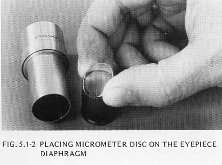
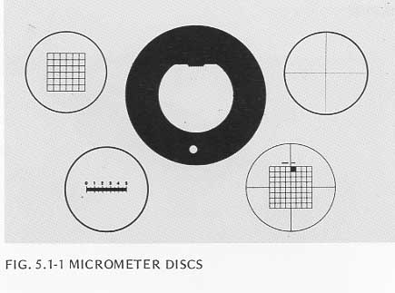
5.1.2 To install a Micrometer Disc in a non-focusable eyepiece, unscrew the diaphragm, place the Disc on the diaphragm with the pattern side down, Figure 5.1-2, and crimp the edge of the mount in four places, Figure 5.1-3, to hold the Disc in place. Screw the diaphragm into the eyepiece until the marks on the disc are in sharp focus. Calibrate the Micrometer Disc using the procedure in section 15 of the Balplan Instruction Manual.

5.1.3 To install a Micrometer Disc in a focusable eyepiece, unscrew the focusable lens, drop the Disc onto the diaphragm with the pattern side down, Figure 5.1-2, and install a spring ring on top of the disc, Figure 5.1-4, to hold it in position. Replace the focusable lens and focus on the Disc. Calibrate the Micrometer Disc using the procedure in section 15 of the Balplan Instruction Manual.
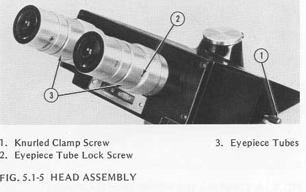
5.1.4 To remove the head from the microscope, grasp the head securely, loosen the knurled clamp screw, Figure 5.1-5, and lift the head up and off the stand.

5.1.5 To adjust the movement of the interpupilary distance mechanism, you must first remove the head assembly from the housing as described in step 3.5.2. Adjust tension on the interpupilary wheel, slide, and gib as required using the nut on top of the slide, Figure 5.1-6. Loosen it to decrease tension, tighten it to increase tension. Specified torque is 12 inch-ounces.
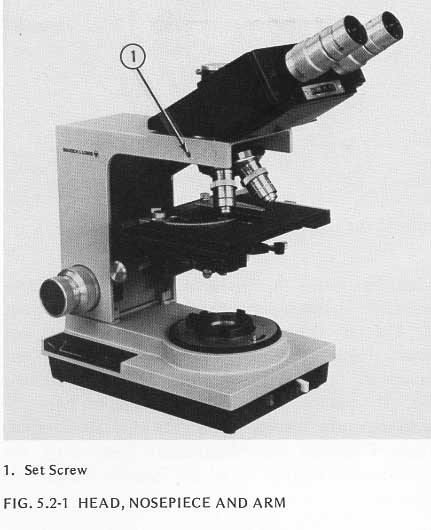
5.2.1 TO remove the nosepiece from the microscope, support the nosepiece with one hand, insert the hexagonal wrench (provided with the microscope) through the hole in the arm and loosen the set screw, Figure 5.2-1.
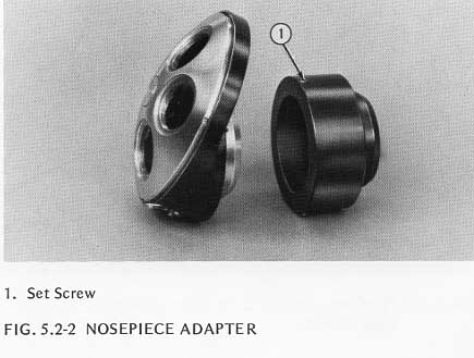
NOTE: If the microscope has a five hole nosepiece with the objective positioned towards the back of the microscope, an adapter will be installed on the nosepiece. Remove this adapter by loosening the two set screws, Figure 5.2-2, and lifting off the adapter.

5.2.2 To adjust tension on the Balplan Ball Detent Index, remove the two screws which hold the spring in place, Figure 5.2-3. Remove the spring, bend it to adjust tension (or replace it if necessary) and reinstall it on the nosepiece. The nosepiece should come to a positive stop at each detent position of the mechanism.
5.2.3 Whenever the nosepiece is removed, clean the nosepiece lens as described in section 4.4.
5.2.4 Replace the nosepiece by raising it into position and supporting it while tightening the set screw. Nosepiece centering should repeat when a force of 32 inch-ounces is applied to the screw.
NOTE: If there is an adapter used with the nosepiece, fasten it to the nosepiece before installation using the two set screws.
All stages offered with the Balplan Microscope are interchangeable on site. Simply remove the stage as directed in step 3.2.1 and install a new one.
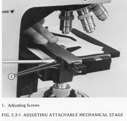
The attachable mechanical stage can be added to a Balplan plain stage at any time. To install the attachable mechanical stage to the plain stage, locate the mechanical stage in the desired position. Fasten it to the plain stage by threading the two screws provided through the holes in the mechanical stage into the threaded holes on either side of the bottom of the plain stage. Tighten the screws securely. If the mechanical stage doesn't operate smoothly, adjust it by loosening the two screws above the Stag Control Knobs. Fold a sheet of typewriter paper twice to make four thicknesses (for thin slides use fewer thicknesses) and place this on the surface of the plain stage under the attachable mechanical stage, Figure 5.3-1. Hold the attachable stage down against the paper, tighten the two screws, and remove the paper.
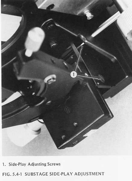
5.4.1 If there is side play in the substage, tighten the two adjusting screws in the side of the substage, Figure 5.4-1. Do not tighten these screws to the point where the substage binds when it is raised or lowered.
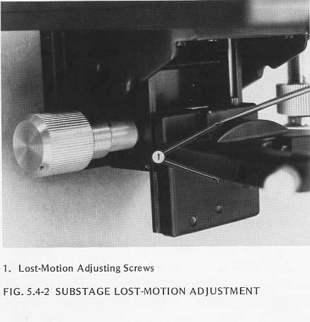
5.4.2 If there is lost motion in raising or lowering the substage, adjust the two screws in the center of the vertical portion of the substage, Figure 5.4-2, until the stage moves smoothly without lost motion or binding from the highest to the lowest position.
5.4.3 The torque on the substage mechanism is controlled by the adjustments in steps 5.4.1 and 5.4.2. Specified torque is 4 to 6 inch-ounces.
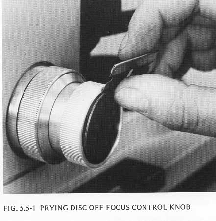
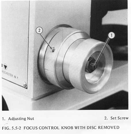
5.5.1 To adjust the torque on the Focus mechanism, position the microscope with its back toward you and remove the disc on the right adjusting knob by slipping a thin blade under the disc and prying it off, Figure 5.5-1. Hold the right Fine Focus Knob and loosen the adjustment knob which is under the disc, Figure 5.5-2.
Set the torque on the Coarse Focus mechanism at 9 to 24 inch-ounces by loosening the Fine Focus Knob, loosening the set screw in the Coarse Focus Knob, Figure 5.5-2, and tightening the right Coarse Focus Knob to increase torque or loosening it to reduce torque as required. When torque is in the specified range, tighten the set screw in the Coarse Focus Knob.
Adjust the torque on the Fine Focus mechanism to 6 inch-ounces. Hold the left Fine Focus Knob and tighten the right Fine Focus Knob to increase the torque or loosen it to decrease the torque. When torque is at specified value, hold the right Fine Focus Knob and tighten the adjusting nut.
Replace the disc on the end of the Fine Focus Knob.
If the torque cannot be properly adjusted, or if the focus mechanism does not work properly even with the specified torque, return it to Bausch & Lomb.
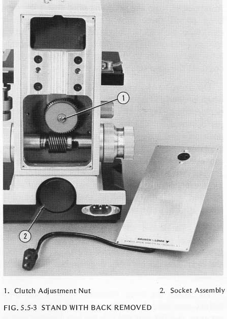
5.5.2 The safety clutch is factory adjusted to prevent the stage from slipping downward during normal use and to prevent damage to the objective or specimen if the stage is inadvertently raised too high. Adjust the clutch if you with to place a heavy object on the stage or if a need for readjustment is indicated by slipping of the stage. To gain access to the clutch adjustment nut, Figure 5.3-3, remove the four screws which hold the back cover on the stand and place the back cover aside. use a 5/16 inch socket nut driver (available at most hardware and radio supply houses) to turn the adjustment nut clockwise to tighten the clutch or counter-clockwise to loosen the clutch. Remember that too loose an adjustment will let the stage drop out of focus with the slightest shock or additional weight, and too tight an adjustment will permit damage to the specimen slides or objectives if the stage is inadvertently raised too high.
5.6.1 High-Intensity Base Illuminator
This illuminator has a factory-centered diaphragm. If it is out of center, or if
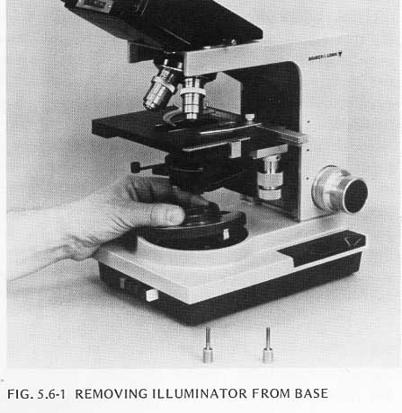
the leaves are not working properly, return the unit to Bausch & Lomb. To remove
the illuminator from the microscope, lift the snap-in upper portion of the
illuminator off the base, Figure 5.6-1, take out the three screws on the
underside, Figure 5.6-2, and separate the base from the microscope.

To replace the lamp in the High-Intensity Illuminator, grasp the flanged end of the socket assembly, Figure 5.5-3, and pull the assembly out of the back of the base. Remove the old lamp by tipping it slightly and turning it counterclockwise to release it from the retaining pins. Insert the new lamp so all three pins are engaged and turn it clockwise to lock it in place. Clean the contact springs (section 4.7) and press the socket assembly into the opening in the rear of the base until it contacts the stop screw.

The stop screw, Figure 5.6-3, is adjustable and, when properly set, positions the lamp for optimum performance. To set the stop screw for best overall performance, place the 10x illuminator in viewing position and use the lowest power eyepieces available. Turn on the illuminator, look through the eyepieces, and move the socket assembly in and out to find the position which provides the most even illumination of the entire field of view. Position the stop screw so the socket assembly stops at this position when pressed into the base.
NOTE: To center the lamp filament, remove the lamp holder assembly from the base. Unscrew the lens retainer and lift out the frosted lens located just in front of the lamp. DO NOT DISTURB THE OTHER LENS. Reinstall the lens retainer to hold the other lens in position, and reassemble the base and lamp holder assembly to the stand. Remove the right eyepiece and replace it with the pinhole eyepiece. Rotate the 10x objective into the viewing position. Open the Field Iris Diaphragm completely by rotating the knurled wheel in the base. Open the condenser diaphragm all the way. When you look through the pinhole eyepiece, you will see the lamp filament. Loosen the four screwson the bottom of the base, adjust the lamp assembly so the filament is in the center of the viewing field as seen through the pinhole eyepiece and tighten the four screws to hold the lamp in this position.
5.6.2 Professional Optilume Illuminator
To replace the lamp, remove the upper portion of the illuminator by turning
slightly counterclockwise and lifting to expose the lamp. Tip the lamp slightly
and turn it counterclockwise to release it from the retaining pins. Insert the
new lamp so all three pins are engaged and turn it clockwise to lock
it in place.
5.6.3 Optilume Illuminator
To replace the lamp, remove the illuminator from the base of the microscope
by twisting it counterclockwise and lifting it carefully to prevent damage
to the ground wire connection between the illuminator and the microscope base.
Unscrew the lamp and replace it with a new one. Replace the illuminator
in the base.
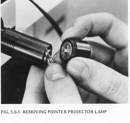
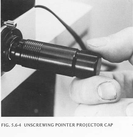
5.6.4 Dual Viewing Adapter
To change the lamp in the Dual Viewing Adapter, unscrew the cap from the back
of the pointer projector, Figure 5.6-4, and the lamp will drop out of the
tube, Figure 5.6-5. Insert a new lamp and replace the cap.