Lubrication of the Balplan Microscope is rarely required. Ball bearings and nylon bushings are used at all critical friction points, and the focus mechanism utilizes self-lubricated ball bearings as thrust and slide bearings. However, occasional lubrication may be required to maintain the Balplan Microscope at optimum operating level.
Grease can best be applied to moving parts with a brush or cotton swab. Always clean the grease brush thoroughly before changin from one type of grease to another. Use a new cotton swab for each different type of grease.
The following tools and supplies are required to performt he specified lubrication operations.
3.1.1 Disconnect any line cords from the power supply.
3.1.2 Expose the focusing mechanism by removing the four screws and lifting off the back cover.
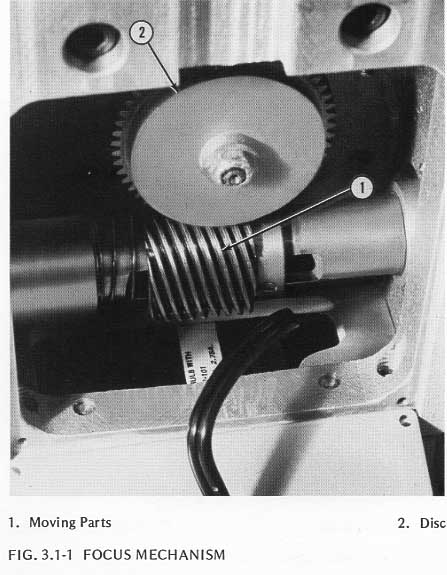
3.1.3 Examine the moving parts, Figure 3.1-1, of the focusing mechanism. If the grease is old and dry, the mechanism should be cleaned with a solvent. Before applying solvent to the mechanism, take off the bottom cover (by removing the three screws), disconnect any electrical cords between the base and the stand and set the base aside.
NOTE: Be careful to avoid damage to any electrical connections.
3.1.4 Apply solvent sparingly to the dried lubricant with a brush and wipe the mechanism with a cloth to remove solvent and lubricant. Repeat as needed.
3.1.5 Lubricate all moving parts with a generous amount of KG-224 (Nyogel) lubricant. Be extremely careful that no lubricant gets on the friction washer of the stage clutch. This washer is located behind the disk, Figure 3.1-1.
3.1.6 Reconnect all electrical wires between base and stand, replace the base on the stand, and replace the back cover.
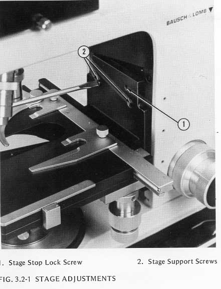
3.2.1 To gain access to the mechanical stage gibs, remove the condenser by pulling it straight out from the substage. Remove the objectives to eliminate interference. Raise the substage as far as possible. Lower the stage until it contacts the lower stop. Remove the two stage screws, Figure 3.2-1. Lift the stage carefully up and out from the stand. A slight upward jolt with the heel of the hand may be required to free the stage from the key.
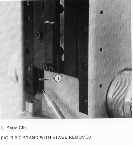
3.2.2 Remove all old dry grease from the stage gibs, Figure 3.2-2, with a cottn swab moistened with solvent.
3.2.3 Lubricate the gibs with KG-208 lubricant.
3.2.4 Reinstall the stage on the microscope stand.
3.3.1 To gain access to the substage gibs, lower the substage until the gibs are exposed.
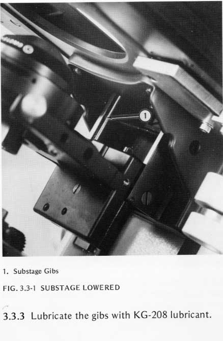
3.3.2 Remove all old dry grease from the gibs and bearing surfaces, Figure 3.3-1, with a cotton swab moistened with solvent.
3.3.3 Lubricate the gibs with KG-208 lubricant.
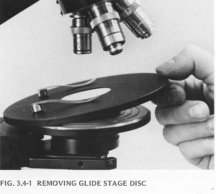
3.4.1 Lower the glide stage until it contacts the bottom stop and lift the upper surface disk off the stage by placing your fingers under the front edge of the surface, Figure 3.4-1, and applying pressure upwards.
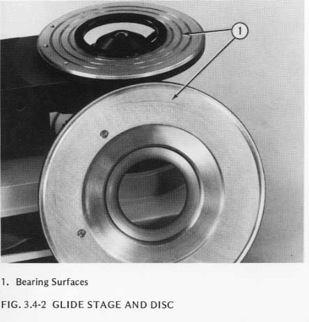
3.4.2 Remove old grease from the bearing surfaces of the disc and the stage, Figure 3.4-2, by applying solvent with a brush, wiping with cloth and repeating as needed to remove all traces of old grease.
3.4.3 Apply sufficient Glide Stage Grease to both bearing surfaces to provide the controlled drag motion which is characteristic of the glide stage.
3.4.4 Replace the surface disc on the glide stage.
3.5.1 Remove the eyepieces and put them aside.
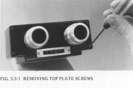
3.5.2 Remove the four screws that hold the top plate to the head, Figure 3.5-1, lift off the top plate and the attached head mechanism.
3.5.3 Remove all old dry grease from the moving parts using a cotton swab moistened with solvent.
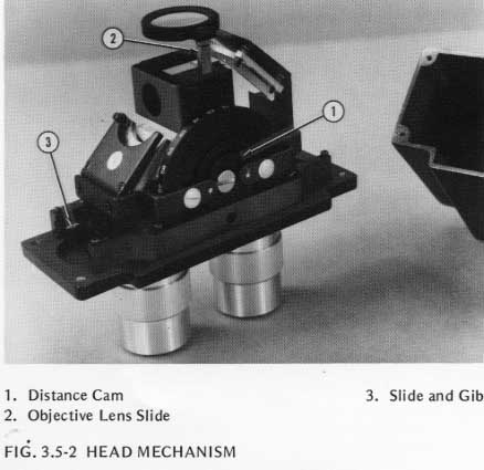
3.5.4 Lubricate the Interpupilary Distance cam and mechanism, Figure 3.5-2, with KG-290 lubricant.
3.5.5 Lubricate the objective lens slide mechanism, Figure 3.5-2, with KG-290 lubricant.
3.5.6 Lubricate the slide and gib, Figure 3.5-2, with KG-208 lubricant.
3.5.7 Reassemble the head.
The surfaces of the substage that move across each other to provide the centering action described in step 2.1.8 require periodic lubrication.
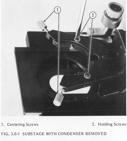
3.6.1 To remove the fork from the stage, first remove the two centering screws, Figure 3.6-1. Then remove the two screws on the underside of the substage, Figure 3.6-1. Now lift the fork up and out of the substage, being careful not to drop the steel ball.
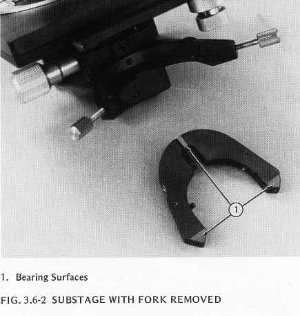
3.6.2 Remove all old grease from the bearing surfaces on the substage and the bottom of the fork, Figure 3.6-2, using a cotton swab moistened with solvent.
3.6.3 Apply a light coat of KG-208 lubricant to the clean bearing surfaces.
3.6.4 Reassemble the fork on the substage by placing the steel ball in its groove and pressing the fork in and down until it is seated. Replace the two screws in the underside of the fork and tighten sufficiently to prevent separation between the bearing surfaces (the upper surface of the substage and the lower surface of the fork). The screws must not be so tight that they restrict the relative horizontal motion betweenthe fork and the substage. Replace the centering screws.
NOTE: The two screws seat against adjustment stop screws accessible through the top of the fork. If the screws cannot be tightened sufficiently to eliminate all separation between the substage and the fork, loosen the adjustment stop screws until all separation is eliminated when the screws on the underside of the substage are seated firmly against the adjustment stop screws. If horizontal motion of the fork is restricted when the two screws are tightened, tighten the adjustment stop screws as required to establish the proper adjustment.