To perform the operations in this section, you will need these tools.
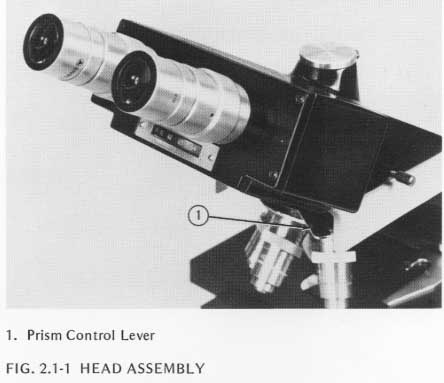
2.1.1 Rotate the nosepiece to bring the highest power objective into the viewing position. If the microscope has a triocular head, make sure to move the Prism Control Lever, Figure 2.1-1, away from you until it reaches a stop. In this position, the movable prism in the head directs all light to the inclined eyepieces for visual use.
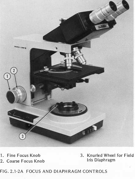
2.1.2 Check the adjustment of the stage stop by placing a blood slide on the stage and bringing it into sharp focus. Ths stop is set properly if the stage can be raised four revolustions of the Fine Focus Knob, Figure 2.1-2A, from the point of sharpest focus without bringing the slide into contact with the highest power objective. If adjustment is needed, use the procedure on page 5-2 of the Balplan Instruction Manual.
2.1.3 Check the adjustment of the substage stop by determining whether a clearance of 0.001 to 0.006 inches exists between the top surface of the stage and the top of the condenser when the substage is raised until it contacts the stop. The condenser should not touch the slide. If adjustment is needed, use the procedure on page 5-4 of the Balplan Instruction Manual.
2.1.4 Rotate the Fine Focus Knob from one end of its travel to the other. It should move smoothly and evenly with positive stops at each end. Specified torque for this control is 6 inch-ounces. If adjustment is needed, use the procedure in Section 5.5.1.
2.1.5 Repeat the procedure in step 2.1.4 using the Coarse Focus Knob, Figure 2.1-2B. Specified torque for this control is 9 to 24 inch-ounces. If adjustment is needed, use the procedure in Section 5.5.1.
2.1.6 Check the adjustment of the stage safety clutch which prevents the stage from slipping down under normal load and protects the objecties and specimen slides from damage if the stage is inadvertantly raised too high. A downward force of about 6 inch-pounds applied to the stage should cause it to slip. If adjustment is needed, use the procedure in Section 5.5.2.
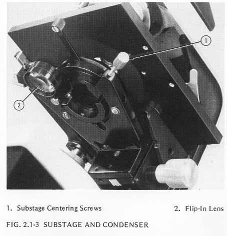
2.1.7 Make sure the 10x objective is in the viewing position and the image is in sharp focus. Remove the eyepiece from the right adapter and insert the pin-hole eyepiece so you can see the condenser. Move the flip-in lens on the bottom of the condenser out of the optical path. If the microscope is equipped with a High Intensity Base Illuminator, close the Field Iris Diaphragm to the half-open position using the knurled wheel, Figure 2.1-2B. Vary the condenser height by moving the substage up and down to obtain the sharpest possible image of the Field Iris Diaphragm on the specimen. Then open the Field Iris Diaphragm until its image is barely visible in the field of view. Center the image of the Field Iris Diaphragm by manipulating the two Centering Screws, Figure 2.1-3, on the substage. If the image cannot be centered by means of the centering screws, return the microscope to Bausch & Lomb.
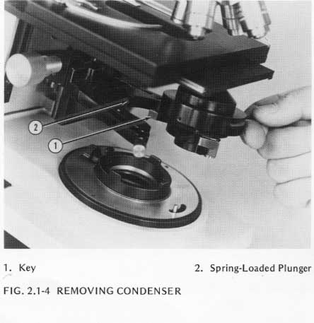
2.1.8 Press the condenser in toward the microscope stand. A spring-loaded plunger, Figure 2.1-4, is used to position the condenser. When the pressure on the condenser is released, the plunger should position the condenser so it is properly centered.
2.1.9 Replace the pin-hole eyepiece with the eyepiece regularly used in the microscope (removed in step 2.1.7). Look through the right eyepiece and make certain that you have the sharpest possible image.
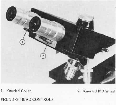
2.1.10 Use the knurled collar, Figure 2.1-5, on the left eyepiece to set the focus of that eyepiece to match the focus of the right eyepiece.
NOTE: When both eyepieces are in proper focus, the difference between the heights of the two eyepiece tubes (with eyepieces removed) should not exceed 1.0 millimeter. If the difference is greater than 1.0 millimeter, return the microscope to Bausch & Lomb.
2.1.11 Remove the right eyepiece and replace it with the reticle eyepiece. Replace the blood slide with the cross-hair slide. Bring the crossline on the slide into sharp focus and position the slide (using the Stage Control Knobs) so the crossline on the slide coincides with the crossline in the eyepiece.
2.1.12 Observe the crossline on the slide while you rotate the knurled wheel, Figure 2.1-5, from one end of the interpupilary distance scale to the other. The point of intersection of the crosslines on the slide should be centered within 0.3 millimeter horizontally and 0.1 millimeter vertically at any setting of the wheel. If it isn't, return the microscope to Bausch & Lomb.
2.1.13 Remove the left eyepiece, replace it with the reticle eyepiece and repeat step 2.1.12 using the left eye.
2.1.14 To check the objectives for parcentricity, use the T-34138-3 Reticle Eyepiece.
Center the point of intersection of the crosslines on the slide in the field of view of the lowest power objective (less than 10x). Parcentricity is correct if the image of the point of intersection falls within 2.0 millimeters of the center of the field of each objective with a magnification of 10x or lower as these objectives are successively rotated into viewing position.
If any of the objectives do not fall within the specified parcentricity, return the objectives to Bausch & Lomb.
NOTE: The focal ranges of the most commonly used objectives are:
| Magnification | N.A. | Focal Range | Working Distance |
|---|---|---|---|
| 2.5x | 0.06 | 0.153mm | 10.0mm |
| 4x | 0.09 | 0.068mm | 10.2mm |
| 10x | 0.25 | 0.009mm | 3.35mm |
| 20x | 0.50 | 0.008mm | 0.79mm |
| 40x | 0.65 | 0.0013mm | 0.56mm |
| 100x | 1.25 | 0.0005mm | 0.14mm |
2.2.1 Place a blood slide on the stage.
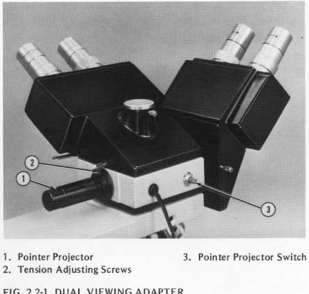
2.2.2 Turn on the pointer, Figure 2.2-1, and move the pointer projector to position the illuminated pointer at a specific location of your choice on the slide.
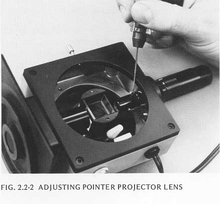
2.2.3 Make certain the image of the pointer is in sharp focus. It may be necessary to adjust the focus by removing the adapter from the microscope, lossening the screw shown in Figure 2.2-2, moving the lens assembly in or out as needed to correct the focus, and retightening the screw.
NOTE: This lens adjustment is a trial and error procedure. Only very slight movement of the lens is required.
2.2.4 Check the tension on the pointer motion mechanism. There should be sufficient tension to prevent the pointer from drifting. Adjust the tension as needed using the tension adjusting screws, Figure 2.2-1.
2.2.5 Check the second head for pointer alignment, parfocality and sharp focus. The maximum allowable difference in the position of the point of the pointer image from one head to the other is 0.5 millimeters.
NOTE: If proper measuring instruments are available and you with to measure the focus, the specified focus is within +1.0 +/- 1.0 diopters.
2.3.1 Move the Prism Control Lever, Figure 2.3-1, toward you until it contacts a stop. All light is now directed to the phototube.
2.3.2 With the crosshair slide on the stage and the reticle eyepiece in the end of the phototube, align the cross on the slide with that in the eyepiece.
2.3.3 Remove the right eyepiece from the microscope and replace it with the reticle eyepiece.
2.3.4 Move the Prism Control Lever away from you until it contacts the stop. This directs all light to the inclined eyepiece.
2.3.5 Observe the crosshair slide through the reticle eyepiece. The intersection of the crosshairs on the slide should lie i the rectangular box at the center of the reticle eyepiece. If it doesn't, return the head assembly to Bausch & Lomb.
2.4.1 Flip the hemispheric condenser lens out of the viewing field.
2.4.2 Replace the right eyepiece of the microscope with the pinhole eyepiece. Make certain the 10x objective is in the viewing position.
2.4.3 Close the Field Iris Diaphragm (in the base of the microscope) as far as it will go by turning the wheel, Figure 2.4-1.
2.4.4 Center the image of the Field Iris Diaphragm usin ghe two centering screws on the substage, Figure 2.4-1.
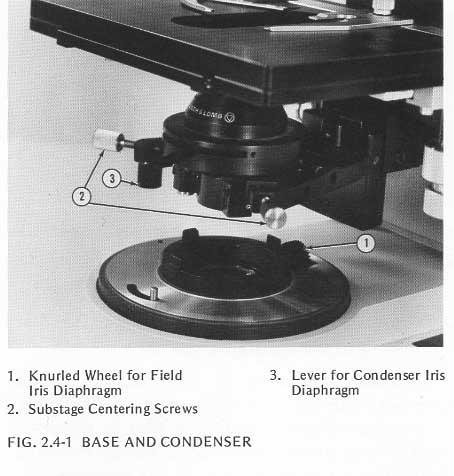
2.4.5 Use the lever, Figure 2.4-1, to adjust the Condenser Iris Diaphragm until the opening is the same size as that in the Field Iris Diaphragm.
2.4.6 Flip in the hemispheric lens.
2.4.7 Center the image of the Condenser Iris Diaphragm on that of the Field Iris Diaphragm using the 3 entering screws on the hemispheric lens on the condenser.
2.5.1 Rotate the 10x objective into the viewing position, and make certain that the Prism Control Lever is away from you as far as it will go so the image appears in the eyepiece.
2.5.2 Place a thin, high-contrast specimen on the stage and bring it into sharp focus as viewed through the right eyepiece.
2.5.3 Move the Prism Control Lever toward you to divert the image from the eyepiece to the camera.
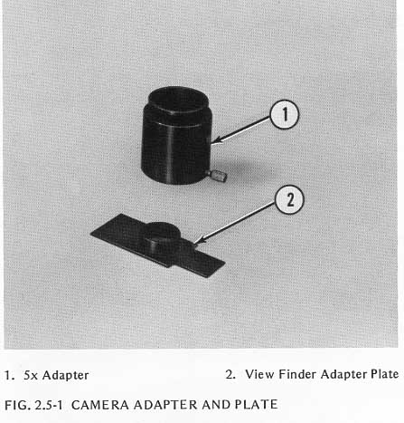
2.5.4 If you are using a 35mm or a 3 1/4 by 4 1/4 camera, pull out the dark slide, open the back of the camera, and place the viewfinder adapter plate, Figure 2.5-1, on the film plane with the cylindrical collar upwards.
2.5.5 Remove the right eyepiece from the eyepiece tube and insert it in the viewfinder adapter plate.
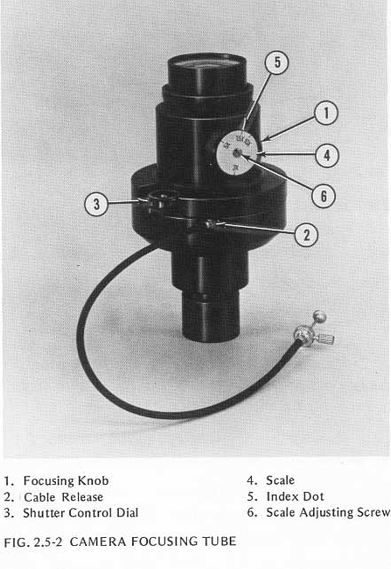
2.5.6 Set the shutter control dial, Figure 2.5-2, at "T" and open the shutter.
2.5.7 Focus the image of the specimen in the eyepiece (with the 4 by 5 camera, focus the image on the ground glass focusing screen) by adjusting the Focusing Knob, Figure 2.5-2, on the Focusing Tube. The image seen through the eyepiece will not be crisp because of the additional 10x magnification of the eyepiece.
2.5.8 The scale on the side of the Focusing Knob should indicate the magnification of the camera opposite the index knob on the Knob. Specified magnification is 3x for a 35mm camera, 5x for a 35mm camera with a 5x adapter, 7.5x for a 3 1/4 by 4 1/4 camera, and 10x for a 4 by 5 camera. If the scale does not indicate the correct magnification, loosen the screw in the center of the scale, Figure 2.5-2, turn the scale until the proper magnification value is opposite the index dot, and tighten the screw securely to hold the scale in position.
2.5.9 Replace the eyepiece in the right eyepiece tube, remove the viewfinder adapter plate and replace the dark slide pulled out in step 2.5.4, and close the back of the camera. Reset the shutter control dial as required.