-
- Disclaimer
- LinuxCNC
- Installing under buster - for
mesa
- Linux Command line
- LinuxCNC acronyms,
abbreviations, special terms, file-types
- Special terms
- File-types
- Create Ethernet connection to
Mesa card (this example used i793)
- testing:
- Change IP to non LAN network
- Write bit file to mesa card
- mesaflash syntax:
- Mesa config wizard
- Connection to 7i84D vis 7i44
- 7i29 notes
- Encoder notes
- INI file notes
- hal file notes
- Nomenclature
- Syntax
- Components
- iocontrol and halui (they
seem to have overlapping functions)
- estop pins
- Machine on-off
- Motion - accepts NML motion
commands, interacts with HAL in realtime
- wj200_vfd
- limit2 component
- PID loop position
- Some basics
- What is PID?
- Understanding
Feedforward
- Tuning Proceedure
- DCBM DC Brushed Motors
- Changing PID
values with Axis Machine/Calibration
- Manual tuning
-
- Velocity vs torque mode
tuning
- Torque Tuning
- Velocity tuning
- Links
- Spindle
- Endocder - hostmot2
- Pins:
- tmp
- Display screens - GUI
- Axis
- Modes of Operations
- Gmoccapy
- gladevcp - added to other
bits
- Homing settings
-
- ini
- Touch Probe for linuxcnc 2.9
- Settings
- auto zero
- Gcode generators
- General CNC notes
Disclaimer
This information HAS errors and is made available
WITHOUT ANY WARRANTY OF ANY KIND and without even the
implied warranty of MERCHANTABILITY or FITNESS FOR A
PARTICULAR PURPOSE. It is not permissible to be read by
anyone who has ever met a lawyer or attorney. Use is confined to
Engineers with more than 370 course hours of engineering.
If you see an error contact:
+1(785) 841 3089
inform@xtronics.com
LinuxCNC
Installing under
buster - for mesa
sources.list lines:
deb     http://buildbot.linuxcnc.org/ buster master-rtpreempt
deb-src http://buildbot.linuxcnc.org/ buster master-rtpreempt
Do not use RTAI real time kernel! - use Preempt-RT
(pae PREEMPT_RT ) - install linux-image-rt-amd64
Linux Command line
Add isolcpus=2,3 ???
Disable cstates in the BIOS/ kernel command line -
intel_idle.max_cstate=0 ??
LinuxCNC acronyms,
abbreviations, special terms, file-types
BLDC - BrushLess DC [motor]
Comp - hal compiler tool
EMCIO - module of linuxcnc for non aixs i/o
EMCMOT module of LinuxCNC that handles the actual motion of the
cutting tool.
hmid - HostMot ID (references the IDROM in HostMot2 firmware) IDROM
specifies what features are included in a specific bitfile and the
functions of the I/O pins
(hmid = Host Mot (Host Motion)
ID = Host based Motion Control -- as in Ethernet host )
hal - Hardware Abstraction Layer - not to be confused with the old
linux hal system of the same name.
ihs - Initial Height Sense
MDI Manual Data Input
NML(Neutral Message Language) - not sure - not in use?
sserial - Smart Serial
Special terms
joint - A joint is one of the movable parts of the machine. not to
be confused with axis.
Kinematics - relationship between world coordinates and joint
coordinates of a machine. There are two types of kinematics. Forward
kinematics is used to calculate world coordinates from joint
coordinates. Inverse kinematics is used for exactly the opposite
purpose.
pin -
File-types
- ini - this file normally named machine-name.ini It is
the base file that points to all the other config files.
LinuxCNC on start up looks for ini file found in a directory in
~/ linuxcnc/configs/machine-name
- pncconf one directory up ls
- vhd - vhdl file???
- xise - files are Xilinx ISE project files - not really
LinuxCNC related
- ucf - ucf files are pin constraint files for Xilinx ISE
- pin .pin files are text representations of the IDROM content
- bit - bitfile used by mesaflash - binary configuration files
for Xilinx FPGAs
Create Ethernet
connection to Mesa card (this example used i793)
Set your jumpers so you are in the Default mode ( 7I93 W4 and
W3 down ) - this will come up with the default IP address
192.168.1.121
You will need mesaflash installed. Linuxcnc must NOT be running.
First set the NIC to use 192.168.1.240 by creating
/etc/network/interfaces.d/local
With contents:
#linuxCNC mesa interface
   auto [your-mesa-NIC-device-name]
   iface [your-mesa-NIC-device-name] inet static
       address 192.168.1.240/24
       hardware−irq−coalesce−rx−usecs 0
Then do
$ ifup your-mesa-NIC-device-name
If the other interface is using the common 192.168.1.0/24 network,
you will probably need to shut it down temporarily with
$ifdown [your-other-NIC-device-name]
testing:
With the 7I93 powered and connected to the Ethernet device used
above, try to ping 192.168.1.121
Then try
mesaflash --verbose --device 7i93 --addr 192.168.1.121
You should get some nice information back - you now should have
Ethernet communications with the mesa card.
Change IP to non
LAN network
In this example, we avoid the common 192.168.1.0/24 network by
setting the Mesa card to 192.168.10.10 and the NIC to
192.168.10.1 both will use the 192.168.10.0/24 network address
space :
$ mesaflash --verbose --device 7i93 --set ip=192.168.10.10
Look at the output - verify that space 2 has ip address:
192.168.10.10
This is now the IP address for the FIXED FROM EEPROM or non DEFAULT
mode - ONLY (DEFAULT mode IP stays the same).
It is time to powerdown and change the W3 jumper to 'up' to set the
card to use FIXED From Eprom mode.
Power the card back up.
Update /etc/network/interfaces.d/local
#linuxCNC mesa interface
 auto [your-NIC-device-name]
iface [your-NIC-device-name] inet static
address 192.168.10.1/24
# address 192.168.1.240/24
# If using intel ethernet that in some cases looses the connection you might need
# hardware−irq−coalesce−rx−usecs 0
Clear the arp cache and restart networking
$ ip -s -s neigh flush all
$ systemctl restart networking
Test again - with
mesaflash --verbose --device 7i93 --addr 192.168.10.10
Write bit file to
mesa card
This example assumes 7i93_svss4_8d.bit firmware would be appropriate
This file is not found in a zip file from Mesa - not in a Deb
package.
$ mesaflash --addr 192.168.10.10 --device 7i93 --write 7i93_svss4_8d.bit
Should write and auto verify -
--$ mesaflash --addr 192.168.10.10 --device 7i93 --reload
If using intel ethernet that in some cases looses the connection,
there should be the following line added in a terminal? ??
sudo ethtool -C eth0 rx-usecs 0
mesaflash syntax:
$ measaflash --help
Do not confuse --serial with --sserial
--verbose is your friend
List pins of the 7i29
$ mesaflash --device 7i93 --addr 192.168.10.10 --readhmid
information about all sserial remote boards
$ mesaflash --verbose --device 7i93 --addr 192.168.10.10 --sserial
Get pins of a mesa board:
$ halcmd show all |grep 7i84
Mesa config
wizard
See http://linuxcnc.org/docs/html/config/pncconf.html
Computer response time -- Check for SMI (Slimy Management
Engine) problems - 120 seconds - ( change to 3600 - or even more )
$ perf stat -a -A --smi-cost -- sleep 120
The management engine is why LinuxCNC does not do well on many
brand new computers. Keep an eye out for coreboot
compatibility - current status is not good(2020).
HP Compaq Elite 8300 Base Model Convertible Minitower PC jitter
measurement :
Max 1,005,664 - jit 5920
Base 33,517 jit 8517
Connection to
7i84D vis 7i44
Mode is set via sserial_port_0=00000000 - 0 = mode-0 , 1
= mode-1 for details see $ man hostmot2
7i29 notes
- CR13 and CR14 light when it starts overriding the duty-cycle
to current limit.
- It is possible to home by hitting a mechanical limit (at the
very lowest speed) which would trigger a following error.
Move back a mm and call it home. more at
https://www.forum.linuxcnc.org/27-driver-boards/39589-7i29-amp-fault-output-pins
- Always use differential encoders" (RS422)
Encoder notes
Index-mask - hardware input that masks the index input signal
INI file notes
1 machine unit = 1 LINEAR_UNITS as set in the [TRAJ] section
hal file notes
Some component instances are generated by things in the ini file.
Nomenclature
Component - software Object?
Parameter - variables - set on instance at startup of component
hal-pin a feature of a component?
signal - equate
Syntax
setp - set pin or parameter
sets - set value of signal
net - connects signal to pin(s) - names signal
unlinkp - disconnect pin from signal
Components
Components all are supposed to have their own man page for pin
descriptions
inihal
iocontrol and
halui (they seem to have overlapping functions)
estop pins
described assuming no pins are yet interconnected:
iocontrol.0.emc-enable-in -- sets the Estop button displayed
in Axis - and
from the docs "Should be driven FALSE when an external estop
condition exists."
(False is the 'in' position)
iocontrol.0.user-enable-out becomes the OPPOSITE of
iocontrol.0.emc-enable-in if you click on the etop-button -
Does NOT change the appearance of the GUI estop button.
From the docs "FALSE when an internal estop condition
exists" (what defines an estop condition here? Are there other
things that can trigger an estop? ) This appears to be the
inverse of halui.estop.is-activated
iocontrol.0.user-request-enable iocontrol.0.user-request-enable (
output that 'PULSES' true if you click on estop button in axis AND
iocontrol.0.emc-enable-in is false (pulses on pulling-out
the GUI estop )
(iocontrol.0.user-request-enable is not completely documented in
the man page (2020))
There is a way (by writing a component) to latch
iocontrol.0.user-request-enable. That being said - it is an extremely
bad
idea to use this to enable a physical estop circuit -
which one should setup a way to disable the physical estop from
linuxcnc - but NOT enable it.
halui.estop.activate on rising edge activates
halui.estop.is-activated
halui.estop.reset on rising edge
resets halui.estop.is-activated
halui.estop levels won't prevent one from overriding with the axis
button.
Machine on-off
halui.machine.is-on ==>
halui.machine.off <==
halui.machine.on <==
Motion - accepts
NML motion commands, interacts with HAL in realtime
spindle.M.speed-out OUT FLOAT - Desired spindle speed in rotations
per minute From g-code S100 command.
All the spindle.M.speed-out.xxx come from g-code (Sxxx).
wj200_vfd
I am told that the cheap RS232 - to - RS485 converters steal
power from RTS and CTS so you might need to set them or use an
external power-supply for reliable operation.
First, you will want to find the page B-4 in the wj200 manual and
set A001, A002, C071, C072, C074, C075, C076, C077, and C078. Then
install mbpoll and test for basic modbus communications
$ mbpoll -a1 -Pnone -d8 -b115200 -r1 -c4 /dev/ttyS0
You should see something like this
-- Polling slave 1... Ctrl-C to stop)
[1]: 0
[2]: 0
[3]: 2
[4]: 0
Note that the driver is loaded with wj200_vfd but the pin names
follow the HAL convention and use wj200-vfd
wj200 defaults to --device=/devS0 --parity none --databits 8
--stopbits 1 --baud 9600
limit2 component
Keeps a float value between min and max - and dx/t under maxv
PID loop position
Some basics
Error = command - measured
Output = Error * PGain + (Integral of Error) * IGain + dError/dt *
DGain + FF0 * command + FF1 * dCommand/dt
Where - FF1 is velocity-feedforward
output = bias + (pgain * tmp1) + (igain * error_i) + (dgain *
error_d);
output += (command * FF0gain) + (cmd_d * FF1gain) + (cmd_dd *
FF2gain);
,.,.
FF0 adds a portion of the command to the output (minimize error
build up - best guess without feedback) normally set to o
FF1 adds a portion the first derivative of the command to the
output (compensates for friction or Motor CEMF ) Normally set
to 1 - adjust output scale so it is true.
FF2 adds a portion of the second derivative of the command to the
output (proportional to acceleration thus a command that is
increasing speed might need a bit of and extra kick to overcome
inertia)
FF3 third derivative -- proportional to jerk (Change in
acceleration )
MIN_FERROR = 1.0 amount of following error (distance in machine
units) allowed at very low velocity
FERROR = 10.0 distance allowed during rapid moves. - permitted
Ferrors are interpolated between these two numbers for speed.
H-bridge Tuning - Servo loop
What is PID?
PID loops are used in all sorts of systems, from temperature
control, to advanced pressure regulators.
P - is Proportional feedback - it takes the error
times a constant and adds it to the drive output. It is similar to
the corrections one makes with the gas pedal of a car - if we are
going a bit too slow, we don't floor it, we just press a proportional
bit harder depending on the magnitude of the error.
The original proportional only controllers go back to Huygens
pendulums and latter Watts flying balls. The math behind all this
was first explored by non other than James Clerk Maxwell in 1868
I - is Integral feedback - it takes the average
error over time times a constant - and adds it to the drive output
( improves fine accuracy)
D - Is Derivative feedback - it takes the change
in error times a constant and adds it to the drive output (
reduces errors when the load suddenly changes)
Understanding
Feedforward
While P(proportional) feed-back works - if you turn it up very high,
it will oscillate - same with D - same with I. So what would
be good is if we can give a drive value that is close to what is
needed and use PID for fine corrections of error. So for any
change in motion - d/dt - we want a value to send that should give
something close to the correct response - that is called feedforward.
This brings us to OUTPUT_SCALE which should be set to the
speed obtained by giving full output to the drive. Thus a
motion request scaled to OUTPUT_SCALE should get us close to the
correct output. If OUTPUT_SCALE is correct, FF1 should
equal 1. This adds to the output value a pretty good guess to
what it should be - and the PID section looks at any errors and
sends correcting additions or subtractions to the output.
Tuning Proceedure
This assumes you already know how to use the calibrate command -
and HALscope.
- Set DEADBAND to 1 machine resolution step * 0.6
- Start with P, I and D FF0 and FF2 at zero
- Set jog speed to 50 mm/min - know where your PHYSICAL ESTOP
switch is and be sure it works - be ready to press it.
- FF1=1 and increase P slowly so things can move - verify
direction, limits, and homing.
- Set P to low value - about 1/4 any possible oscillation.
Oscillations can allso be caused by OUTPUT_SCALE being way
off.
- Set OUTPUT_SCALE to encoder.N.velocity when pwmgen is
pedal-to-the-metal. We are finding the maximum speed the table
can move! This means changing things in ini so you can
move things at dangerous speeds - work smart -
this is dangerous - if you don't know exactly
what you are doing - don't )
- If you are OK with the danger - for the axis under tuning
you will need to temporarily greatly increase FERROR,
MAX_VELOCITY. In the [DISPLAY] section set MAX_LINEAR_VELOCITY
to something insane. (I could not change this via the
calibration window - had to edit the ini file and restart)
- MAX_ACCELERATION - plot the velocity feedback in
Halscope and max out acceleration. The slope of that will be the
physical max - you will want to set to something like 90% of
this (Perhaps a bunch less? No reason to
hotrod..)(MAX_ACCELERATION has to be correct for tuning to work
- if you ask a PID loop to accelerate things faster than
possible - the numbers saturate and clip).
- Getting FF1 correct and accurate is key - other things won't
work if it is wrong. It will be correct if you measure - no
guessing.
- Be sure jog speed is quite low - start with 50mm/min
- Set up the HALscope to look at f-error, motor-pos-command, and
pos-relative for the axis you are working on.
- Start up the Calibrate window.
- Increase P slowly until you get a slight overshoot - something
that looks like a damping factor of 0.4-0.7 - increase jog
speed.
- Double the jog speed and repeat the step above. - keep
doubling until you get to something like 1000mm/min
- FF1 - Start with a very low number - 0.01 Increase slowly -
Tune to eliminate start and stop over/under shoots (about 0.005%
of P).
- Set FF2 so that the actual position does not lead or lag the
commanded position during acceleration
- Increase I until you start to see oscilations in FERROR
Once this tuning is finished - set [TRAJ]MAX_LINEAR_VELOCITY
approx 20% higher than the axis settings.
G-code is sort of ignorant of acceleration - one would want
to set MAX_ACCELERATION to something sane.
Don't forget to return FERROR, MAX_VELOCITYt
MAX_LINEAR_VELOCITY to operating settings.
Checks - compare pwmgen.N.scale to OUTPUT_SCALE
DCBM DC Brushed
Motors
A DC motor gets a speed from this equation where ω is the rotation
in radians:
ω = V/k - TR/k^2
k and R are constants - but k in the torque term it is squared so
less of a factor (torque load slows things down a bit) so I see this
as mostly a velocity input device. The slowing of the speed by tool
force has to be corrected by the PID loop. We test at full
posible speed to find OUTPUT_SCALE so that the second term of the
above equation is insignificant.
speed for the test?
buzzyness?
increase P speed? damping?
Set D below buzzyness - ( a few wiggles in
f-error plot ? )
Set FF1 so that the actual position does not lead or lag
the commanded position at full speed
Set FF2 so that the actual position does not lead or lag
the commanded position during acceleration
Increase P as much as possible without causing overshoot
Increase I below but close to instability. No slow
hunting oscillations..

Changing PID
values with Axis Machine/Calibration
This window makes temporary live changes of PID parameters - that
you enter - after you press 'test'. One has to press Test
- try the setting - then press Cancel to make
the next change - rinse - repeat..
While in test - one has to create the move via Jog.
Normally you would monitor joint.N.f-error with the halscope...
Manual tuning
Set I and D to zero - set P to 1/2 value where it starts to
oscillate ( overdamped - no overshoot )
Increase I to instability - set to 1/2
increase D to instability - set to 1/2
Ziegler–Nichols method
https://en.wikipedia.org/wiki/Ziegler%E2%80%93Nichols_method
FF1, its the most important tuning number for velocity mode drives
Before tuning - remove all the PID maxerror lines in the hal file ..
FF1 should be set to within 1/10 1%
For a velocity mode servo (when the drive is tuned properly) D is
_not_ appropriate and FF1 is arguably the most important tuning
parameter.
Velocity vs torque
mode tuning
They are NOT the same - so two subsections below
For both modes -
If OUTPUT_SCALE is set so PID output is in machine units per second
then the PID values are "normalized" so inch and mm machines will
have comparable PID numbers and things
like FF1 will make sense (FF1 will be 1.00 if the scaling is
correct). Watch pwmgen.N.value and encoder.N.velocity
with the halmeter and change OUTPUT_SCALE until they are close to
matching.
For spindles
Torque Tuning
Start with FF1=0 and FF2 = 0 and I=0
Chose a small amount of P (say 50 = full torque with 1/5" error)
Then increase D until it gets too "buzzy" and then back off about
30% on D
Then increase P until you get oscillations and again back off about
30%
Then adjust FF2 so that you neither overshoot or undershoot during
acceleration (the FF2 setting is inertia dependent so its better to
do this with a typical table load)
Finally increase I until motion becomes unstable (Watch out for WIDE
oscillations here)
and back off about 50%
Another take - Increase D to oscillation - then set at 1/2
Increase P to oscillation - then set to 1/2
Add FF2 to tune out accel-undershoot - and decel-overshoot.
Carefully - add I to oscillation - then set at 1/4
Velocity tuning
For a velocty PID loop probably the most important part is FF0
If the PID feedback, command and output are all in RPM, FF0 should
be 1.0)
If you have only FF0(all other PID terms=0), you are running open
loop
(because the PID output is just FF0*Command)
Using the FF0 feedforward term make the PID output approximately
correct before any
feedpack is applied. This makes the P and I terms have less work to
do...

Links
http://support.motioneng.com/Downloads-Notes/Tuning/default.htm
Servo tunning:
https://forum.linuxcnc.org/10-advanced-configuration/32367-servo-tuning-detailed-how-to
https://gnipsel.com/linuxcnc/tuning/servo.html
Spindle
# set the encoder to non-quadrature simple counting using A only.
setp hm2_7i93.0.encoder.04.counter-mode true
http://linuxcnc.org/docs/devel/html/drivers/hostmot2.html#sec:hm2-encoder
G33 centric -
spindle.N.at-speed
motion.coord-error OUT BIT TRUE when motion has
encountered an error, such as exceeding a soft limit
motion.coord-mode OUT BIT
spindle.N.revs
spindle.0.speed-out-abs comes from g-code s command..
wj200-vfd.0.commanded-frequency sets motor speed..
- two speeds thus hm2_7i93.0.encoder.04.scale set via
mux2
# set the HAL encoder to 60 pulses per revolution.
setp hm2_5i25.0.encoder.02.scale
400
# set the encoder to quadrature counting using A and B .
setp hm2_5i25.0.encoder.02.counter-mode false
# connect the HAL encoder outputs to LinuxCNC.
#net spindle-position-soft encoder.0.position =>
motion.spindle-revs
net spindle-velocity hm2_5i25.0.encoder.02.velocity =>
motion.spindle-speed-in
net spindle-index-enable hm2_5i25.0.encoder.02.index-enable
<=> motion.spindle-index-enable
#spindle_orient
net spindle-position-0to1 hm2_5i25.0.encoder.02.position =>
orient.position => orient-pid.feedback =>
motion.spindle-revs => near.0.in1
net orient-angle motion.spindle-orient-angle =>
orient.angle
net orient-enable motion.spindle-orient => mux2.0.sel =>
or2.0.in1 => and2.0.in1 => orient-pid.enable =>
orient.enable => and2.1.in0
#####setp timedelay.0.on-delay 2
#####setp timedelay.1.on-delay 1
#######net spindle-in-position near.0.out => timedelay.0.in
=> timedelay.1.in
#######net spindle-in-position5 timedelay.1.out =>
and2.1.in1
#######net spindle-in-position8 or2.2.out =>
parport.0.pin-02-out
net spindle-in-position10 or2.2.out =>
parport.0.pin-02-out
net spindle-in-position9 and2.1.out =>
or2.2.in1
net spindle-in-position8 or2.2.in0 <=
motion.spindle-locked
net spindle-in-position7 parport.0.pin-13-in => or2.1.in0
#####net spindle-in-position2 timedelay.0.out => and2.0.in0
#####net spindle-in-position2 timedelay.0.out => or2.1.in1
net spindle-in-position3 or2.1.out => and2.0.in0
net spindle-in-position4 and2.0.out =>
motion.spindle-is-oriented
setp orient-pid.maxoutput 0.25
setp orient-pid.Pgain
10
# 4.1
setp orient-pid.Igain
0
setp orient-pid.Dgain
0
setp orient-pid.FF1
0.0013
setp orient-pid.FF2
0.0002
setp orient-pid.deadband 0.001
setp near.0.difference 0.01 # (3.6 degrees)
############# End Spindle Encoder #############
#and then connect the encoder to the 7I76's encoder input
net spindle-vel-cmd-rps
<= motion.spindle-speed-out-rps
net spindle-vel-cmd-rps-abs <=
motion.spindle-speed-out-rps-abs
net spindle-vel-cmd-rpm
<= motion.spindle-speed-out
net spindle-vel-cmd-rpm-abs <=
motion.spindle-speed-out-abs
net
spindle-enable
motion.spindle-on => or2.0.in0 ######*#
net
spindle-cw
<= motion.spindle-forward #temp test orientate
net
spindle-ccw
<= motion.spindle-reverse
net
spindle-brake
<= motion.spindle-brake
net
spindle-at-speed
=> motion.spindle-at-speed
#These lines in hal gave sensible readings on the halscope. Note
the scale now the same as scale in the ini file.
#These settings get pwm on gpio008 working
setp hm2_5i25.0.pwmgen.00.output-type 1
setp hm2_5i25.0.pwmgen.00.scale 36
setp hm2_5i25.0.pwmgen.pdm_frequency 5000000
setp hm2_5i25.0.pwmgen.pwm_frequency 5000
net spindle-vel-cmd-rps => mux2.0.in0
net selected-spindle-vel-cmd-rps mux2.0.out =>
hm2_5i25.0.pwmgen.00.value
#change num_pwmgens=0 to num_pwmgens=1(note this cannot be
selected in Pncconfig 5i25/7i76)
setp hm2_5i25.0.gpio.025.invert_output true
#net spindle-enable => hm2_5i25.0.pwmgen.00.enable #comment out
for orient mod
net spindle-enable => or2.0.in0
net selected-spindle-enable or2.0.out =>
hm2_5i25.0.pwmgen.00.enable ######*#=> hm2_5i25.0.gpio.017.out
Endocder -
hostmot2
Pins:
(s32 out) count
Number of encoder counts - up and down - since the previous reset.
(float out) position
Encoder position in position units (count / scale).
(float out) velocity
Estimated encoder velocity in position units per second.
(float out) velocity-rpm
Estimated encoder velocity in position units per minute.
(bit in) reset
When this pin is TRUE, the count and position pins are set to
0. (The value of the velocity pin is not affected by
this.) The driver does not reset this pin to
FALSE after resetting the count to 0, that is the user's job.
(bit in/out) index-enable
When this pin is set to True, the count (and therefore also
position) are reset to zero on the next Index (Phase-Z) pulse.
At the same time, index-enable is re‐
set to zero to indicate that the pulse has occurred. (Is This is an
edge triggered event? ) The motion component sets
spindle.S.index-enable (in/out) to TRUE at the beginning of a
spindle-synchronized move (Thus zeroing the spindle count - at the
start of the spindle-synchronized move. )
(s32 out) rawcounts
Total number of encoder counts since the start, not adjusted for
index or reset.
(bit out) input-a, input-b, input-index
Real time filtered values of A,B,Index encoder signals
(bit in) quad-error-enable
When this pin is true quadrature error reporting is enabled.
when false, existing quadrature errors are cleared and error
reporting is disabled
(bit out) quad-error
This bit indicates that a quadrature sequence error has been
detected. It can only be set if the corresponding
quad-error-enable bit is true
(u32 in) hm2_XXXX.N.encoder.sample-frequency
This is the sample frequency that determines all standard encoder
channels digital filter time constant (see filter parameter)
(u32 in)
hm2_XXXX.N.encoder.muxed-sample-frequency
This is the sample frequency that determines all muxed encoder
channels digital filter time constant (see filter parameter) This
also sets the encoder multiplex‐
ing frequency
(float in) hm2_XXXX.N.encoder.muxed-skew
This sets the muxed encoder sample time delay (in ns) from the
multiplex signal. Setting this properly can increase the
usable multiplex frequency and compen‐
sate for cable delays (suggested value is 3* cable length in feet
+20)
(bit in) hm2_XXXX.N.encoder.hires-timestamp
When this pin is true the encoder timestamp counter
frequency is ~10 MHz when false the timestamp counter frequency is
~2 MHz. This should be set true for fre‐
quency counting applications to improve the resolution. It should be
set false when servo thread periods longer than 1 ms are used.
Parameters:
(float r/w) scale
Converts from 'count' units to 'position' units.
(bit r/w) index-invert
If set to True, the rising edge of the Index input pin triggers the
Index event (if index-enable is True). If set to False, the
falling edge triggers.
(bit r/w) index-mask
If set to True, the Index input pin only has an effect if the
Index-Mask input pin is True (or False, depending on the
index-mask-invert pin below).
(bit r/w) index-mask-invert
If set to True, Index-Mask must be False for Index to have an
effect. If set to False, the Index-Mask pin must be True.
(bit r/w) counter-mode
Set to False (the default) for Quadrature. Set to True for
Step/Dir (in which case Step is on the A pin and Dir is on the B
pin).
(bit r/w) filter
If set to True (the default), the quadrature counter needs 15 sample
clocks to register a change on any of the three input lines (any
pulse shorter than this is
rejected as noise). If set to False, the quadrature counter
needs only 3 clocks to register a change. The default encoder
sample clock runs at approximately 25
to 33 MHz but can be changed globally with the sample-frequency or
muxed-sample-frequency pin
(float r/w) vel-timeout
When the encoder is moving slower than one pulse for each time that
the driver reads the count from the FPGA (in the hm2_read()
function), the velocity is harder to estimate. The
driver can wait several iterations for the next pulse to arrive, all
the while reporting the upper bound of the encoder velocity, which
can be accurately guessed. This parameter specifies how long
to wait for the next pulse, before reporting the encoder
stopped. This parameter is in seconds.
(s32 r/w) hm2_XXXX.N.encoder.timer-number
(default: -1)
Sets the hm2dpll timer instance to be used to latch encoder
counts. A setting of -1 does not latch encoder counts. A
setting of 0 latches at the same time as
the main hostmot2 read. A setting of 1..4 uses a time offset
from the main hostmot2 read according to the dpll's timer-us
setting.
Typically, timer-us should be a negative number with a magnitude
larger than the largest latency (e.g., -100 for a system with
mediocre latency, -50 for a system
with good latency).
If no DPLL module is present in the FPGA firmware, or if the encoder
module does not support DPLL, then this pin is not created.
When available, this feature should typically be enabled.
Doing so generally reduces following errors.
tmp
Servo-loop link
https://forum.linuxcnc.org/24-hal-components/38141-closing-the-servo-loop-with-hal-mesa-7i76
Building LinuxCNC
https://gnipsel.com/linuxcnc/uspace/debian9-eth.html
GUI Frontends
axis - solid
Gscreen (uses gladeVCP) PathPilot??
TkLinuxCNC GUI
hazzy new
Display screens -
GUI
Qtvcp is an infrastructure to display a custom CNC screen or control
panel in LinuxCNC. It displays a UI file built with the QTDesigner
screen
Gmoccapy
nativeCAM seems like a key feature.
Axis
As of 2.8 put a file in ~/linuxcnc/misc/axicrc to fix up things.
Default screensize:
 max size root_window.tk.call("wm","geometry",".","1900x1200")
# or - To have Axis open up at the maximum size for
your screen use:

#maxgeo=root_window.tk.call("wm","maxsize",".")
#fullsize=maxgeo.split(' ')[0] + 'x' + maxgeo.split(' ')[1]
#root_window.tk.call("wm","geometry",".",fullsize) #for now
root_window.tk.call("wm","geometry",".","1600x1000")
Manual [F3]- manual control tab
The axis can be selected and jogged here.
Touch Off
The Axis GUI rather hides what is happening under the hood. (and
it also makes it too easy to get it wrong)
The touch-off button brings up a dialog, and in that you can
select a drop-down. The default is P0 which is the current
G54-G59-3 coordinate System.
P0 runs G10 L20
What then happens is G10 L20 PN, where N is the
dropped-down coordinate system
See
https://lrak.net/wiki/gcode.html
Tool Touch Off
G10 L10 Pn where n is the current tool number
MDI(Manual Data Input)[F5]
gladevcp - added to other bits
gladevcp gives a fairly useable interface to create GUIs..
To test -
gladevcp_demo -H custom.hal gvcp-panel.ui
During test - run
halcmd show all
This gets you the pin names.. you can also run
halmeter. The names are not consistent -
gvcp-panel.motor_current gets set as gladevcp.motor_current
in custom_gvcp.hal
The ini file tells gvcp where to look for the python handlers.py
file in this line: GLADEVCP= -u handlers.py -H
gvcp_call_list.hal gvcp-panel.ui
Homing settings
ini
[TRAJ]
NO_FORCE_HOMING =
HOME =
POSITION_FILE =
[JOINT]
HOME =
HOME_OFFSET =
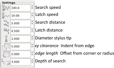
Touch Probe for
linuxcnc 2.9
https://forum.linuxcnc.org/49-basic-configuration/29187-work-with-probe?start=640#276444
- install using the instructions from
https://github.com/verser-git/probe_screen_v2.8
/python
/psng
need to be copied or linked in to ~/linuxcnc/configs/machine-name/
Settings
- start VERY conservatively.. with something the probe can push..
auto zero
Gcode generators
https://github.com/linuxcnc/simple-gcode-generators
https://www.warrensbrain.com/gcode-to-english-translator.html
Email