
This information HAS errors and is made available
WITHOUT ANY WARRANTY OF ANY KIND and without even the
implied warranty of MERCHANTABILITY or FITNESS FOR A
PARTICULAR PURPOSE. It is not permissible to be read by
anyone who has ever met a lawyer or attorney. Use is confined to
Engineers with more than 370 course hours of engineering.
If you see an error contact:
+1(785) 841 3089
inform@xtronics.com
Because there are different standards...
| Pin numbers > |
1 | 2 | 3 | 4 | 5 | 6 | 7 | 8 | 9 |
|---|---|---|---|---|---|---|---|---|---|
| Sino RS-422 Ditron-compatible |
A' |
GND |
B' | Shield | R'/Z' | A | +5V | B | R/Z |
| Vevor | A' |
GND |
B' | |
Z' | A | +5V | B | Z |
| ToAuto, Jing, and others. | +5V | GND |
A | B | |
||||
| Yuheng Optics Co RS-422 |
GND black |
Z' | A |
+5V red |
B brown |
Z |
Yuheng 9D color code:
1 - A' Blue
2 GND - black
3 B' brown
4 shield
5 Z' yellow
6 A White
7 +5 red
8 B green
9 Z grey
1 2 3 4 5
6 7 8 9
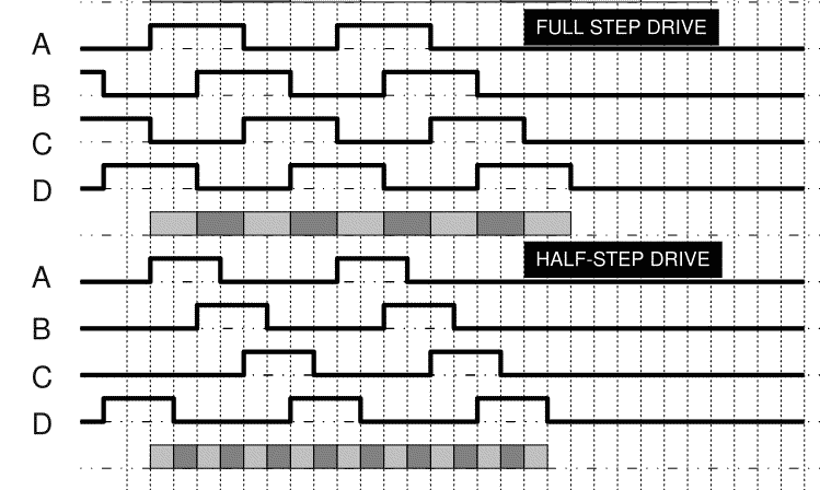
Both optical and magnetic (similar to magnetic tape) encoders produce a quadrature wave form and and index pulse that lets the receiving electronics keep track of the position of a rotating shaft or linear position (linear position most often has an index pulse every so often and may have a home position output as well. An improved version uses gray-coded encoding (see below).
A Rotary encoder's quadrature waveform output

A schematic of a Rotary encoder's quadrature encoding disc

A Rotary encoder's quadrature encoding disc

A gray code encoding disc

8 bit gray encoder

In the schematic above, a sine-wave is transmitted via a rotary transformer to the rotating reference winding, the 'rotor'. If the rotor is perpendicular to one of the 'stators' none of the signal is received by that stator. If the rotor is parallel a stator, that stator will receive the full signal. Thus the amplitude and polarity of the outputs reveals the quadrant and position within the quadrant. The sub quadrant position is based on the ratio of the sine vs cosine voltages. SIN θ / COS θ = TAN θ, where θ = shaft angle.
There is more than a little hand-waving about how these signals are detected. Comparing the amplitude of the reference vs stator signals could be accomplished with peak detection, but such a system would have poor noise immunity and thus would have poor accuracy. Instead a four quadrant multiplier is used as peak detection throws out a lot of signal information.
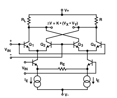
Using a multiplier, the reference is compared to the signals throughout the whole cycle.
It is also explained that the 'phase information' provides
position information - this is true, but misleading - it is better
said that the polarity of the signals indicate the quadrant the
rotor is in at anyone time.
Similar to the resolver (see above) but with three stators 120°
apart.
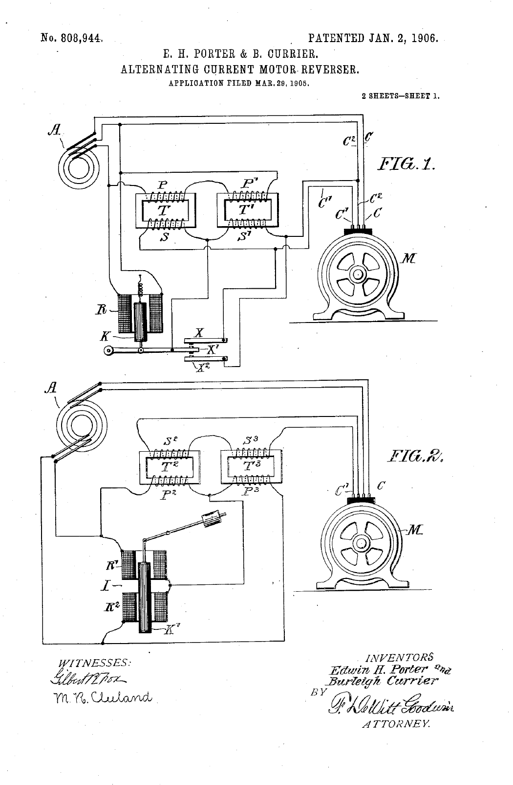
Originally a massive electric motor (US pat 808944 from 1906 Contactless AC-motor reverser) - these were used to control motor position. For details find a used copy of Herceg, Edward E. (1976). Handbook of Measurement and Control. Schaevitz Engineering. LCCN 76-24971
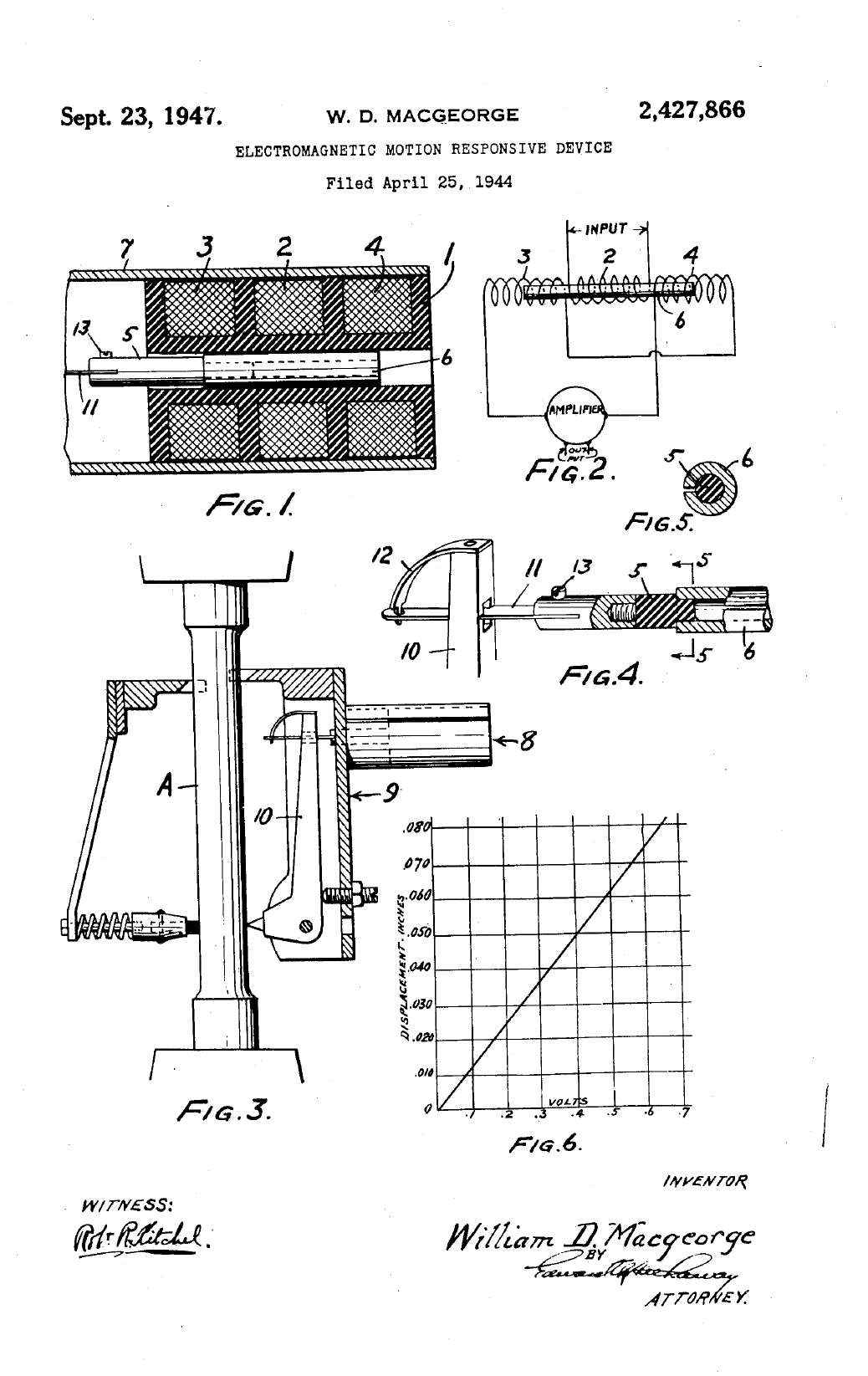
LVDTs are the standard of linear contact measurement - frictionless - repeatability 0.01um. The core moves linearly inside a transformer consisting of a center primary coil and two outer secondary coils wound on a cylindrical form. The primary winding is excited with an ac voltage source (typically several kHz), inducing secondary voltages that vary with the position of the magnetic core within the assembly. The core is usually threaded in order to facilitate attachment to a non-ferromagnetic rod which, in turn, is attached to the object whose movement or displacement is being measured.
One does not have to spend $1k to get the electronics for a LVDT
head - just get an AD698 which can also be used to build a simple
system that works with a half-bridge and full-bridge heads.
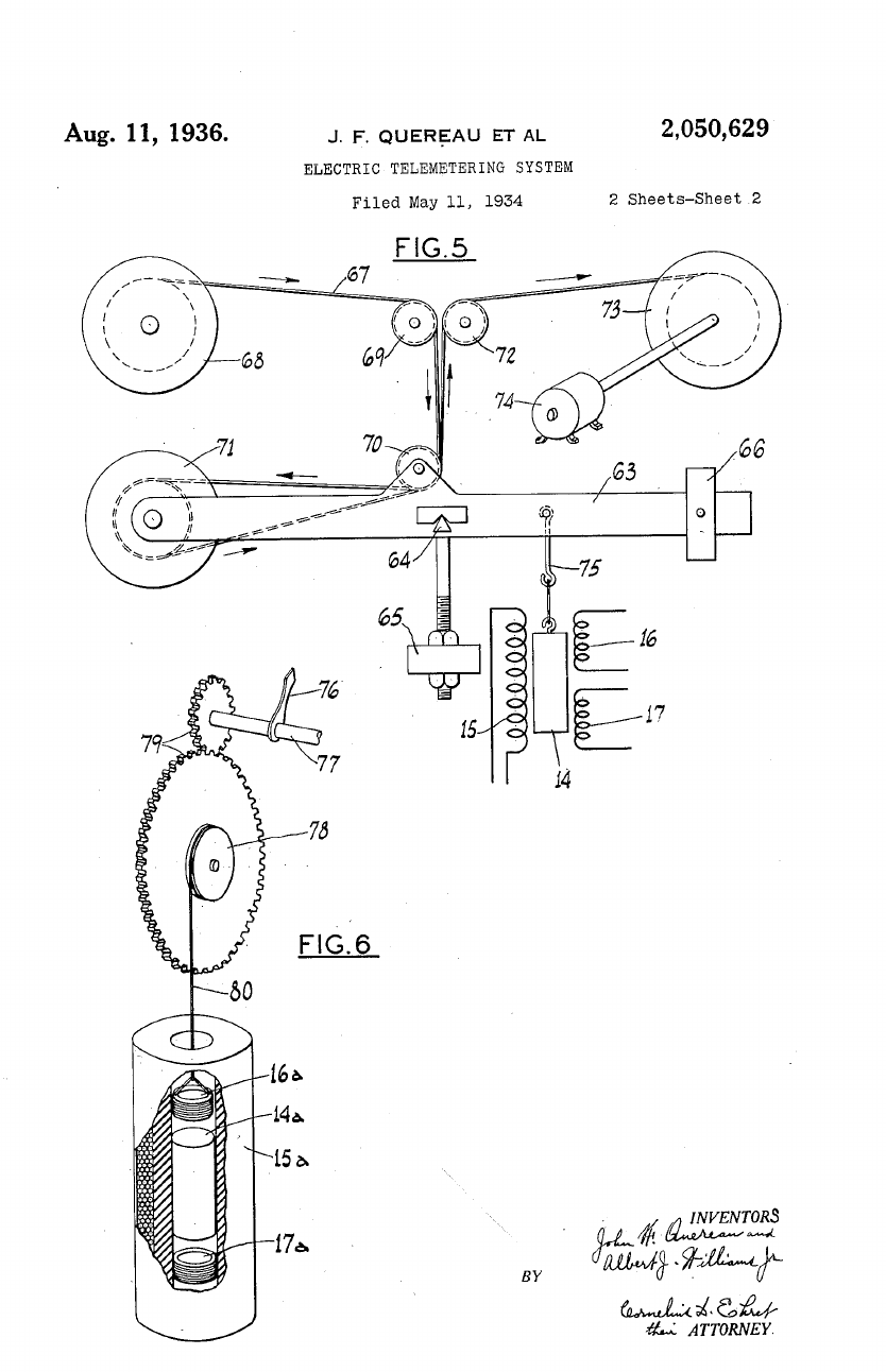
Key patent diagrams:
LVDT-1906-808944.png
LVDT-1934-2050629.png
LVDT-1940-2196809.png
LVDT-1947-2427866.png
Paper - need copy:
The linear variable differential transformer
H Schaevitz - Proc Soc Stress Anal, 1947
This information HAS errors and is made available
WITHOUT ANY WARRANTY OF ANY KIND and without even the
implied warranty of MERCHANTABILITY or FITNESS FOR A
PARTICULAR PURPOSE. It is not permissible to be read by
anyone who has ever met a lawyer or attorney. Use is confined to
Engineers with more than 370 course hours of engineering.
If you see an error contact:
+1(785) 841 3089
inform@xtronics.com
Both optical and magnetic (similar to magnetic tape) encoders produce a quadrature wave form and and index pulse that lets the receiving electronics keep track of the position of a rotating shaft or linear position (linear position most often has an index pulse every so often and may have a home position output as well. An improved version uses gray-coded encoding (see below).
A Rotary encoder's quadrature waveform output
A schematic of a Rotary encoder's quadrature encoding disc
A Rotary encoder's quadrature encoding disc
A gray code encoding disc
8 bit gray encoder
In the schematic above, a sine-wave is transmitted via a rotary transformer to the rotating reference winding, the 'rotor'. If the rotor is perpendicular to one of the 'stators' none of the signal is received by that stator. If the rotor is parallel a stator, that stator will receive the full signal. Thus the amplitude and polarity of the outputs reveals the quadrant and position within the quadrant. The sub quadrant position is based on the ratio of the sine vs cosine voltages. SIN θ / COS θ = TAN θ, where θ = shaft angle.
There is more than a little hand-waving about how these signals are detected. Comparing the amplitude of the reference vs stator signals could be accomplished with peak detection, but such a system would have poor noise immunity and thus would have poor accuracy. Instead a four quadrant multiplier is used as peak detection throws out a lot of signal information.
Using a multiplier, the reference is compared to the signals throughout the whole cycle.
It is also explained that the 'phase information' provides
position information - this is true, but misleading - it is better
said that the polarity of the signals indicate the quadrant the
rotor is in at anyone time.
Similar to the resolver (see above) but with three stators 120°
apart.
Originally a massive electric motor (US pat 808944 from 1906 Contactless AC-motor reverser) - these were used to control motor position. For details find a used copy of Herceg, Edward E. (1976). Handbook of Measurement and Control. Schaevitz Engineering. LCCN 76-24971
LVDTs are the standard of linear contact measurement - frictionless - repeatability 0.01um. The core moves linearly inside a transformer consisting of a center primary coil and two outer secondary coils wound on a cylindrical form. The primary winding is excited with an ac voltage source (typically several kHz), inducing secondary voltages that vary with the position of the magnetic core within the assembly. The core is usually threaded in order to facilitate attachment to a non-ferromagnetic rod which, in turn, is attached to the object whose movement or displacement is being measured.
One does not have to spend $1k to get the electronics for a LVDT
head - just get an AD698 which can also be used to build a simple
system that works with a half-bridge and full-bridge heads.
Key patent diagrams:
LVDT-1906-808944.png
LVDT-1934-2050629.png
LVDT-1940-2196809.png
LVDT-1947-2427866.png
Paper - need copy:
The linear variable differential transformer
H Schaevitz - Proc Soc Stress Anal, 1947
| Top Page | wiki Index |
(C) Copyright 1994-2020
All trademarks are the property of their respective owners.
| Top Page | wiki Index |
(C) Copyright 1994-2020
All trademarks are the property of their respective owners.