Disclaimer

This information HAS errors and is made available WITHOUT ANY WARRANTY OF ANY KIND and without even the implied warranty of MERCHANTABILITY or FITNESS FOR A PARTICULAR PURPOSE. It is not permissible to be read by anyone who has ever met a lawyer or attorney. Use is confined to Engineers with more than 370 course hours of engineering.
If you see an error contact:
+1(785) 841 3089
inform@xtronics.com


  1. Disclaimer
  2. FreeCAD  freecad
    1. Hints
    2. Path tool Bar
      1. Create Job dialog
        1. General tab
        2. Output tab
        3. Setup Tab
        4. Tools Tab
        5. Workplan tab
        6. Op Defaults tab
      2. Operations
      3. Millface
        1. Face
      4. Adaptive clearing
      5. Threadmill
      6. Dressups
      7. Tool bit
      8. Variables

FreeCAD  freecad

Insert mark into Report view:
 FreeCAD.Console.PrintError("\n\n++++++++++++++++++++++ MARK ++++++++++\n") 

Hints

If sketches can't be opened - check the through/tip settings of the body.

Path tool Bar

Important to start off with origins placed from the edge of where the stock will be - FreeCad is not good at letting one change things after more items have been created.. makes errors appear..

We want the origin to be on the STOCK  - not the part..

Create Job dialog

When we create the 'path job'  click on the corner to the stock created and select set origin.


General tab


Output tab

Set processor to LinuxCNC (most likely)

Arguments - this supports changing the --preamble and --postamble

--preamble "G17 G40 G49 G64 P0.015 G80 G90 G94 G97 G98 f100"
--postamble "G17 G90 M5 M9 M2"

Arguments can also do --bcnc --no-comments --translate_drill  which you are unlikely to use.

Order by - most likely the default (fixture ) will work for you

Split output - creates separate files for each operation.

Setup Tab

Tools Tab

Workplan tab

Op Defaults tab


Operations

clearance_height (should be called clamp_height)is the top of all vises, clamps and other obstruction in the whole job. Any move AT OR ABOVE clearance height is assumed to be clear and can go at RAPID speed.

safe_height (should be called retract-height) is the top of the stock material. Any move BELOW safe height must be at FEED rate except for retraction. Moves between safe height and clearance can be at RAPID speed within the operation but aren't guaranteed clear between ops.

start_depth is the top of the model.

Millface

Face

 BoundaryShape: Shape to use for calculating Boundary - one of 'boundbox' (a 3D box) 'face region' 'perimeter' 'stock' - cutter must stay inside boundary?

ClearEdges: Clear edges of surface (Only applicable to BoundBox)
ExcludeRaisedAreas: Exclude milling raised areas inside the face.
 Offset Pattern: Clearing pattern to use. (Select in which manner the horizontal movements should be done.)

Adaptive clearing

Select faces from above - not the profiling face.

Operation Type - Profiling vs clearing?  - not clear what this means.  

Step over percent - Percent of diameter of end mill

There is an Accuracy vs performance slider - which end is which?  Turns out max accuracy is to the left.

Helix Ramp Angle

Helix Cone angle

Helix may Diameter

Lift Distance - lift over already cleared areas

Keep Tool Down Ratio Could be to prevent tool wear?

Force clearing inside out  - Start at center vs an X-Y path?

Finishing Profile - could mean a few things

Use outline
Stop - I suppose for if the calculation hangs?

Threadmill

The threadmill tool has what they call the crest - this is probably crest-width ( FCS) The width of the crest. threadmill
The diameter of a threadmill cutter could be the actual diameter or the diameter if the angle theoretically came to a perfect point( they don't - always a radius).

The corner of the threadmills which don't come to a point - there is always a radius. The diameter of the tool might be the actual diameter or the theoretical diameter (if it did come to a point)??


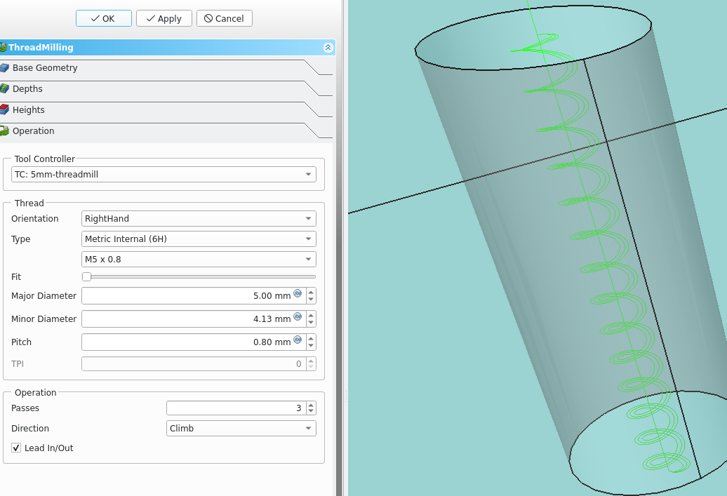
As of 2023 (0.21.0 )it works but won't simulate?

Defaults to bottom up threading (what you want)

Passes can be increased to reduce tool flex.

Fit lets one tweak for fit.


Dressups

Boundary dress-up allows restricting the extent of a path to a smaller part of the object. For example, restricting a profile path to just one face or part of the model.

DressupDogBone dresses up an existing path to overcut corners on inside angles of a profile or contour operation. A cylindrical cutter cannot cut all the way into an acute corner without colliding with the model. In certain cases, it may be preferable to violate the model and ensure that the material at the corner is removed. This is especially necessary if parts are going to intersect/interlock with each other.

DressupDragKnife dresses up an existing path to add corner actions and edge extensions for drag knife cutting.

DressupLeadInOut ????????  Start and finish of cut.

DressupRampEntry

DressupTag  dresses up an existing path (usually a 2D contour cutting path) to leave tags that hold the part in place.

Tool bit

file ext

.fctb = Freecad tool-bit file

.fctl = freecad Tool Library

Variables

Safe height  = Retract height  (nothing safe about it - should be changed)
Clearance height = Clamp height - 35mm?


Top Page wiki Index

Email

(C) Copyright 1994-2023
All trademarks are the property of their respective owners.