
This information HAS errors and is made available
WITHOUT ANY WARRANTY OF ANY KIND and without even the
implied warranty of MERCHANTABILITY or FITNESS FOR A
PARTICULAR PURPOSE. It is not permissible to be read by
anyone who has ever met a lawyer or attorney. Use is confined to
Engineers with more than 370 course hours of engineering.
If you see an error contact:
+1(785) 841 3089
inform@xtronics.com
By definition, No. 36 AWG is 0.0050 inches in diameter, and No. 0000 is 0.4600 inches in diameter. The ratio of these diameters is 92, and there are 40 gauge sizes from No. 36 to No. 0000, or 39 steps. Using this common ratio, wire gauge sizes vary geometrically according to the following formulas.
d = diameter
n = AWG gauge number
A = cross-sectional area
or equivalently

The gauge can be calculated from the diameter using

(NB: if you are calculating AWG with a calculator that does not support logarithms to a definable base, then you can apply the Change of Base equivalent equation)
and the cross-section area is

Sizes with multiple zeros are successively larger than No. 0 and can be denoted using "number of zeros/0", for example 4/0 for 0000. For an m/0 AWG wire, use n = −(m−1) = 1−m in the above formulas. For instance, for No. 0000 or 4/0, use n = −3.
In part from Reference Data for Engineers: Radio, Electronics, Computer and Communications 7th Ed At 20 C
| AWG | Dia Inch | Cir Mil | Dia mm | Area Inch2 | lb/kft | ohms /kft |
Ohms /km |
CU Max free-air Amps |
CU Max enclosed Amps |
|---|---|---|---|---|---|---|---|---|---|
| 32 | 0.008 | 63.2 | 0.20 | 4.964E-05 | 0.19 | 164.1 | 538.4 | .53 | 0.32 |
| 30 | 0.010 | 100.5 | 0.25 | 7.894E-05 | 0.30 | 103.2 | 338.6 | .86 | 0.52 |
| 28 | 0.013 | 159.8 | 0.32 | 1.255E-04 | 0.48 | 64.9 | 212.9 | 1.4 | 0.83 |
| 26 | 0.016 | 254.1 | 0.40 | 1.996E-04 | 0.77 | 40.81 | 133.9 | 2.2 | 1.3 |
| 24 | 0.020 | 404.0 | 0.51 | 3.173E-04 | 1.22 | 25.67 | 84.22 | 3.5 | 2.1 |
| 22 | 0.025 | 642.4 | 0.64 | 5.046E-04 | 1.94 | 16.14 | 52.95 | 7.0 | 5.0 |
| 20 | 0.032 | 1,021.5 | 0.81 | 8.023E-04 | 3.09 | 10.15 | 33.30 | 11.0 | 7.5 |
| 18 | 0.040 | 1,624.3 | 1.02 | 1.276E-03 | 4.92 | 6.385 | 20.95 | 16 | 10 |
| 16 | 0.051 | 2,582.7 | 1.29 | 2.028E-03 | 7.82 | 4.016 | 13.18 | 22 | 13 |
| 14 | 0.064 | 4,106.7 | 1.63 | 3.225E-03 | 12.43 | 2.525 | 8.284 | 32 | 17 |
| 12 | 0.081 | 6,529.9 | 2.05 | 5.129E-03 | 19.77 | 1.588 | 5.210 | 41 | 23 |
| 10 | 0.102 | 10,383.0 | 2.59 | 8.155E-03 | 31.43 | 0.999 | 3.985 | 55 | 33 |
| 8 | 0.128 | 16,509.7 | 3.26 | 1.297E-02 | 49.98 | 0.628 | 3.274 | 73 | 46 |
| 6 | 0.162 | 26,251.4 | 4.12 | 2.062E-02 | 79.46 | 0.395 | 1.296 | 101 | 60 |
| 4 | 0.204 | 41,741.3 | 5.19 | 3.278E-02 | 126.35 | 0.248 | 0.8136 | 135 | 80 |
| 2 | 0.258 | 66,371.3 | 6.54 | 5.213E-02 | 200.91 | 0.156 | 0.5118 | 181 | 100 |
| 1 | 0.289 | 83,692.7 | 7.35 | 6.573E-02 | 253.34 | 0.123 | 0.4035 | 211 | 125 |
| 0 | 0.325 | 105,534.5 | 8.25 | 8.289E-02 | 319.46 | 0.0983 | 0.3225 | 245 | 150 |
| 00 | 0.365 | 133,076.5 | 9.27 | 1.045E-01 | 402.83 | 0.0779 | 0.2556 | 283 | 175 |
| 000 | 0.410 | 167,806.4 | 10.40 | 1.318E-01 | 507.96 | 0.0618 | 0.2028 | 328 | 200 |
| 0000 | 0.460 | 211,600.0 | 11.68 | 1.662E-01 | 640.53 | 0.04901 | 0.1608 | 380 | 225 |
Max ambient 60°C
| AWG | Dia Inch | Cir Mil | Dia mm | Area Inch2 | lb/kft | ohms /kft |
Ohms /km |
CU Max free-air Amps |
CU Max enclosed Amps |
|---|---|---|---|---|---|---|---|---|---|
| 32 | 0.008 | 63.2 | 0.20 | 4.964E-05 | 0.19 | 199.587 | 654.613 | .53 | 0.32 |
| 30 | 0.010 | 100.5 | 0.25 | 7.894E-05 | 0.30 | 125.521 | 411.690 | .86 | 0.52 |
| 28 | 0.013 | 159.8 | 0.32 | 1.255E-04 | 0.48 | 78.941 | 258.915 | 1.4 | 0.83 |
| 26 | 0.016 | 254.1 | 0.40 | 1.996E-04 | 0.77 | 49.647 | 162.833 | 2.2 | 1.3 |
| 24 | 0.020 | 404.0 | 0.51 | 3.173E-04 | 1.22 | 31.223 | 102.407 | 3.5 | 2.1 |
| 22 | 0.025 | 642.4 | 0.64 | 5.046E-04 | 1.94 | 19.636 | 64.404 | 7.0 | 5.0 |
| 20 | 0.032 | 1,021.5 | 0.81 | 8.023E-04 | 3.09 | 12.349 | 40.504 | 11.0 | 7.5 |
| 18 | 0.040 | 1,624.3 | 1.02 | 1.276E-03 | 4.92 | 7.767 | 25.473 | 16 | 10 |
| 16 | 0.051 | 2,582.7 | 1,29 | 2.028E-03 | 7.82 | 4.884 | 16.020 | 22 | 13 |
| 14 | 0.064 | 4,106.7 | 1.63 | 3.225E-03 | 12.43 | 3.072 | 10.075 | 32 | 17 |
| 12 | 0.081 | 6,529.9 | 2.05 | 5.129E-03 | 19.77 | 1.932 | 6.336 | 41 | 23 |
| 10 | 0.102 | 10,383.0 | 2.59 | 8.155E-03 | 31.43 | 1.215 | 3.985 | 55 | 33 |
| 8 | 0.128 | 16,509.7 | 3.26 | 1.297E-02 | 49.98 | 0.764 | 2.506 | 73 | 46 |
| 6 | 0.162 | 26,251.4 | 4.12 | 2.062E-02 | 79.46 | 0.481 | 1.576 | 101 | 60 |
| 4 | 0.204 | 41,741.3 | 5.19 | 3.278E-02 | 126.35 | 0.302 | 0.991 | 135 | 80 |
| 2 | 0.258 | 66,371.3 | 6.54 | 5.213E-02 | 200.91 | 0.190 | 0.623 | 181 | 100 |
| 1 | 0.289 | 83,692.7 | 7.35 | 6.573E-02 | 253.34 | 0.151 | 0.494 | 211 | 125 |
| 0 | 0.325 | 105,534.5 | 8.25 | 8.289E-02 | 319.46 | 0.120 | 0.392 | 245 | 150 |
| 00 | 0.365 | 133,076.5 | 9.27 | 1.045E-01 | 402.83 | 0.095 | 0.311 | 283 | 175 |
| 000 | 0.410 | 167,806.4 | 10.40 | 1.318E-01 | 507.96 | 0.075 | 0.247 | 328 | 200 |
| 0000 | 0.460 | 211,600.0 | 11.68 | 1.662E-01 | 640.53 | 0.060 | 0.196 | 380 | 225 |
First, avoid the most common error in house wiring - hanging a 120Vac outlet off of a 3 conductor (L1,L2,N) 220Vac cable. It is dangerous! To do something like that you need a 4 conductor cable - (L1,L2,N,G) to provide a safety ground that is _NOT_ carrying any current.
The table below will not support any reduced ground cables and is for _Copper_wire_only_!. If you run aluminum wire you need to consult the manufacturer's data sheets and be sure to understand terminal block treatments! This table also in no way compensates for length of run! This table is not for wires packed in conduit - wires need to dissipate heat!
| Normal COPPER
House Wiring Gauge Consult your building inspector because your location will have a specific building code! |
|
|---|---|
| Circuit Maximum Amperage |
Minimum COPPER wire gage |
| 15A | 14AWG |
| 20A | 12AWG |
| 30A | 10AWG |
| 40A (45A*) | 8AWG |
| 55A (60*) | 6AWG |
| 70A (80*) | 4AWG |
| 95A (100*) | 2AWG |
| Alternate marked *
is NOT to NEC code for 60 degree wiring (inside romex). |
|
UL 1007 - PVC Stranded Tinned -40-105C 300V@80C AWM
UL 1015 - PVC Stranded Tinned -40-105C 600V@80C MTW
UL1018 -
PVC
600V@80C
UL 1199 Teflon
PTFE insulated
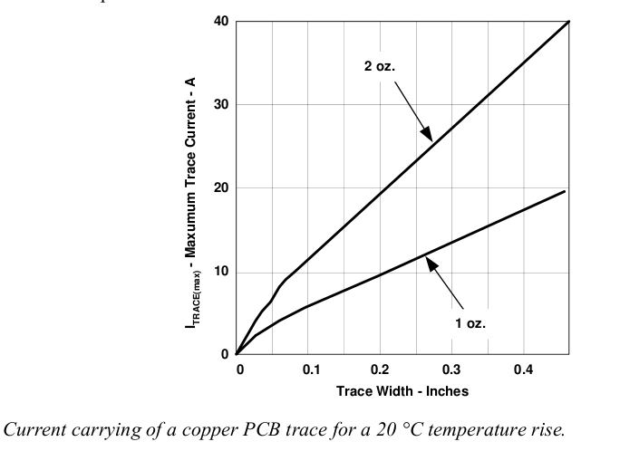
This chart can diverge from what you see for many reasons.
H. W. Preece’s Investigation way back in 1884 provided a way to calculate the fusing current of a wire based on its diameter.

or

Where:
| Material | k for d in cm | Melting point°C | Resistivity (Ω-m) at 20 °C | Coefficient* |
|---|---|---|---|---|
| Silver | 1900 | 961.78 | 1.59×10⁻⁸ | .0038 |
| Copper | 2530 | 1084.62 | 1.72×10⁻⁸ | .0039 |
| Aluminum | 1870 | 660.32 | 2.82×10⁻⁸ | .0039 |
| Iron | 777.4 | 1538 | 1.0×10⁻⁷ | .005 |
| Tin | 405.5 | 231.93 | 1.09×10⁻⁷ | .0045 |
| Platinum | 1277 | 1768.3 | 1.1×10⁻⁷ | .00392 |
| Lead | 340.5 | 327.46 | 2.2×10⁻⁷ | .0039 |
| Tin/lead solder | 325.5 | 183 | 1.44x10⁻⁷ | .0035 |
There should be a relationship between resistivity, melting temperature and k. Remember that the electrical resistivity ρ (Rho (letter)) of a material is given by:

where
 is
the length of the piece of material (measured in meters, m);
is
the length of the piece of material (measured in meters, m);
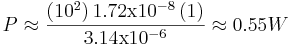
First, an example using the formula in the above section to determine the wattage dissipated in a 1 meter length of 12 gage copper wire at 10A.
Rearrange to solve for R

Remembering that P = I2R

Substituting in where:


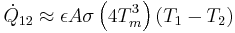
Note, in practical terrestrial cases, convective and conductive heat losses will dominate radiative losses. The following are appropriate for only two situations. One, where you have to install cabling in regions with exceptionally thin atmospheres, such as in vacuum vessels or piping. The other, is where the current densities are sufficiently high for the wire to glow - radiative transfer may then dominate the other loss mechanisms and the following can be used.
Now, to figure the temperature rise per watt in steady-state conditions.
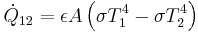
Where :
 Net radiant
energy
Net radiant
energy 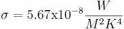 Stefan-Boltzmann constant
 When T1 and T2 are not very
different, it is convenient to linearize the equation by factoring
the term ,  to obtain:

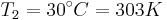
When ,  and Tm
is the mean of T1 and T2
and Tm
is the mean of T1 and T2
Written again as
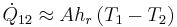
Where
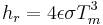 or
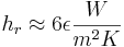
Radiation heat transfer coefficient with the units ,
or
Radiation heat transfer coefficient with the units , 
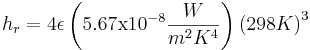
Emissivity is always a fuzzy number that depends on details like surface finish and for copper can vary from 0.7 to .88 but for electrical work 0.4 works most of the time. Give it large error bands!
The surface area of our wire is

Our power is 0.55 Watts and , 
![0.55W = \left ( 0.4 \right ) \left (
0.0644m^2 \right ) \left [ \sigma T_1^4 - \left ( 5.67
\mathrm{x} 10^-8 \frac{W}{m^2 K^4} \right )
\left(303K\right)^4 \right ]](images/2388a79c8a850082438407c490fcc71d.png)
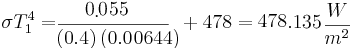
![\sigma T_1^4 = \left[ \frac {0.55}{
\left ( 0.4 \right ) \left ( 0.0644 \right )} + 478\right]
\frac{W}{m^2}](images/f1ff38675970c520837d57d4e4dfd800.png)
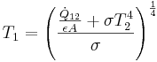
![T_1 = \left [ \frac{480.1}{5.67
\mathrm{x}10^{-8}} \right]^{\frac{1}{4}} = 303.35K](images/ad477f2c7f8f1a19073beeda08519e5e.png)
or a rise of 0.034 C
We can solve for T1 generally:
Black used to be the colour of the live wire in ordinary cables in Europe (as it still as it is in the USA). This is because the very first power wires were insulated by strips of linen soaked with guttappercha ( a good organic insulator) and natural rubber filled with soot. Hence: black colour for the dangerous one. The neutral wires weren't insulated at all, just bare copper wire. Later they got a grey coating (less soot in them), still later blue as artificial dyes came up in Europe.
In ordinary 230 V AC household cables, e.g. for kitchen devices, TV-sets, small machines etc.:
In three phase 400 V cables
L1, L2, L3 were labeled formerly as R, S, T respectively. Motor inputs were U, S, V. The corresponding cold ends of the motor windings were called X, Y, Z, usually shorted together in a "star" or "Y" connection arrangement.
In older three phase cables the grey lead was also black so when installing cables, it was difficult to determine the direction of rotation. In cables older than, say, 60 years the PE lead was red, in Switzerland even more recently.
Blue may be (and is frequently) used for any purpose, especially for switched power, can't be sure that it's neutral. Other colours may be used for any purpose. Green/yellow may not be used for anything else but PE.
In the UK and those areas adopting British standards, red was universally live and black was neutral (with green earth if sleeved)for both fixed wiring and flexes from before the war, until 1971. Then the green with yellow stripe earth was introduced. (mitigating risks of mistake with red green colour blindness) At the same time brown was introduced for live and blue for neutral in new flexes. (3 phase went from red-white-blue to red-yellow-blue, but very few were seriously affected by this. There was also agreement that the colours in this order represent the sequence of positive half cycles for correct rotation. This was a more useful change.) In the UK from late 2005 fixed-wiring also changed to to brown & blue ( this change is sometimes referred to as euro-harmonization). At the same time 3-phase colours went from red/blue/yellow with a black neutral to brown/black/grey with a blue neutral. So now both blue and black can either be live or neutral depending on the age of the installation, leading to some potentially expensive and dangerous errors when old and new systems co-exist.
Prior to Unification in 1989, much of East Germany had many appliances of the older German colour code, with gray and white or black as current carrying colours and red earth. Live and neutral polarity is not preserved in the Shcucko socket system, and it is important to be very careful with older equipment from this era of unknown provenance.
In DC (direct current) electronics applications, Black is most
often ground and Red most often positive. More wire about see - telco color codes
(C) Copyright 1994-2019
All trademarks are the property of their respective owners.