Wells Index Serial
#20567 Model 810
- Wells Index Serial #20567 Model 810
- Wells machine Specifications
-
-
- Pendant
- Motherboard
- Mesa cards (Looks like mesa
is the deal?)
- Linuxcnc - see linuxcnc
- Scales (linear encoders)
- Spindle
- Spindle motor
- Hitachi WJ200-022SF inverter
- WJ200-022SF
Settings
- Spindle encoder
- Drive DC supply
- Homing Notes
- Servo motors
- Distance between pinon gear
base and motor base:
- Gear ratio
- 2 are IIC Inc. MT30U4-36
(M4-2959A) - now all 3
- The other Milltronics
MT30U4-38 -Spindle
- Encoders on the motors:
dynamics research corp encoder 152-021-500-18UJ
- Lubes
- Way covers
- Tramming the nodd
- Kwik-Switch - on the tapers
page
- Ball-screws
- Saddle and table ball-screw
bearings
- Z-axis ball screw
- Spindle
- Sandwich Assembly
- Important things not to be
missed
- Adjusting the end-play
- BACK GEAR - not really -
does not reverse!
- Removal of 3hp Spindle motor
- Procedure for removing
sandwich assembly for replacing oil seal in back gear
housing and other repairs.
- Reassembly of gear box
- Removinge motor variable
drive pulley spring assembly
- To remove vertical spindle
pulley (drive cone pulley - CAM housing)
- Assembling Cam housing
- Brake
- TO ADJUST THE SPINDLE
BRAKE:
- Spindle speeds
- Motor magnetic brake
- Bearings
- Size Weight
- Moving
- History
- Removing The Table
- Ram (AKA Overarm)
- Turret
- wiring
- Notes for similar machine
-
- INSTRUCTIONS FOR CHANGING
SPINDLES IN THE FOLLOWING MODELS 745. 747. 756, 757,
845, 847, 856, 857,760, 860, and 887.
- PROCEDURE FOR FREEING UP
BACK GEAR TO DIRECT DRIVE 745, 756, 760, 845, 856,
747, 757, 860, 847, and 857
- Precision limit switches
Wells machine
Specifications
Table size 228x 1168mm [9" x 46"] 5/8" T-slots
Travels
- x 812.8 [32"] ?? Wishful or not with full way
engagement? 660.4[26"] with way engaged
- y 304.8[12"] possible 305
- quill 132[5.25??]
- Knee 431;8 [17"]
- Overarm/ram 533.4[21"]
Original color ASA 49 grey
Pendant
VistaCNC http://www.vistacnc.com/b07_pendant_P1/pendant_p1A.htm
Motherboard
HP8300 -CMT ( have docs)
Mesa cards (Looks
like mesa is the deal?)
https://mesanet.com
"Anything I/O" does not meant what it says - only digital
signals.
- 7I93 Ethernet-2-two AIO-50pin card can drive
up to 4 7I29s $89
- 7I29 AIO50 to dual H-bridge driver - dual Encoder
Front (power side) are frame ground (only connect to motor
cable shield wire) $299 2x250ma .5A
- 7I37TA AIO-to-16/8 I/O opto isolated - breakout - no LED $79
- 7I44 Host-2 Eight Channel RS-422/485 interface/ RJ45
$69
- 7I84 RS422-to-32/16 + 2 quad counters - Breakout no LEDs
$79
- 7I73 RS422-to-16/4-2A (+4 quadrature counters? )
NO-breakout - no LEDs $49 - needs 40 and 34 pin breakouts
- 7I66-8 RS422-to-16/8 remote isolated digital - with
breakout + LED $79
Scales (linear
encoders)
SINO - have install manual
Need 3 scales
X KA300-720(1um)(RS422) Ali-ex $134.75 need length = 677 - extra
45mm
Y KA300-370(1um) Ali-ex 124.12 ???? need length =350 - extra 20mm
existing mount holes 470
Z KA200-140 (1um) Ali-ex $195.86 need length = spec=132(wrong)
actual 136
Aston Machinery Equipment Store?
All 9pin - Can you put together a package quote?
KA-200 supporting plate
KA300 supporting plate
KA300D enclosure or X
Guangzhou Lokshun CNC Equipment Ltd.
https://www.sino-ld.com/en/
Address: No. 17, Yunjun Road, Huangpu District, Guangzhou
Postal code: 510530
Tel: +86-020-66839300
Fax: +86-020-66839301
Spindle
Spindle motor
Model 10348-BL1964E Frame
AFA-912S
3-phase 60hz 3 HP
Max Ambient 50 - Continuous duty cycle.
Insulation code F (155°C - motor surface temp is 30° cooler - so
max surface is 125°C )
RPM (@60hz) 1800
Insulation System B (130°C )
230V - 9.*A
460V 4.9A
Hitachi
WJ200-022SF inverter
WJ200-022SF
Max baud 15,200
Brake resistor 35 - 100ohms 400Watt?
W -H - D 108 128 170.5 Needs 100mm top and bottom clearance and 50
mm sides..
Power in 30A
power Wire - MTW or UL1015
https://www.houwire.com/products/belden.asp/
https://www.distributorwire.com/blog/machine-tool-wire/
WJ200-022SF
Settings
The manual is seriously sub-optimal - Hitachi should be
embarrassed
PTC - settings
C005 - set 19 - ONLY if you have a 3k trip PTC thermistor
in place.
C085 - 93%
C085 sets scale factor for PTC - works backwards
- 150 trips at a lower resistance..
100% - trips at 3.19K
90% trips at 3.52K (10% higher)
KTY81/222 thermistor is 2k-2.04K @25°C with a TC of 0.79%/°K
Temp to Resistance KTY81/222
| °C |
R |
| 20 |
1941 |
| 25 |
2020 |
| 30 |
2100 |
| 40 |
2267 |
| 50 |
2441 |
| 60 |
2623 |
| 70 |
2812 |
| 80 |
3009 |
| 90 |
3214 |
| 100 |
3426 |
| 110 |
3643 |
| 120 |
3855 |
| 125 |
3955 |
| 130 |
4048 |
| 140 |
4208 |
| 150 |
4323 |
Main settings :
b037 04 unlocks params
A001 03 Freq-source = ModBus input
A002 03 Run command source = ModBuss
A003 60 Base frequency- motor rated frequency where we have max
torque and HP
A004 66 MAX freqiency - give a bit of head room.
A051 DC braking
A082 230 motor voltage AVR
C071 10 modbus baud rate 115,200
C072 01 ModBus addr
C074 00 No parity
C075 01 Stop bit
C076 01 Communication error = decelerates and trips
C077 00.0 Com error timeout 0 = disabled
C078 00 Com wait time - how long before reply
L terminal to deteSet 19 in C005.
H003 2.2 (2.2 or 3.7 ? ) KW rating of motor - ( could
increase )
H004 04 Motor poles
P012 ???
F001
F002 03 acceleration time sec
F003 03 deceleration time sec
b082 0.5 in hz Start frequency
Important to run the auto-tuning on the motor, ideally with the
belt off or in neutral drive position. (One can do a static
autotune if it isn't possible to disengage the drive)
Auto-tuning
set A001 02
set A002 02
set F001 60
Verify H003 motor size in kwh
verify H004 motor poles
verify A003 base frequency - (motor frequency)
verify A082 AVR voltage - motor voltage
verify A051 00 is off for tuning DC braking
H001 02 - Enabled with motor rotation
Press RUN - The motor will hum and then cycle up to 75% of
speed twice. When completed the display will s
_ _ _ o - completed or _ _ _ _ Failed
Press stop
Set H002 02
- set the VFD run to stop and then press the reset key on the VFD.
Go into the programming mode and set H002 = 02 and save, this will
load the motor auto tuning data.
Restore A001 A002 to 03
# lose all settings warning !!!!!!!!!!!!!!!
Factory reboot
Set B087 = 2
#####################
Might need some of below - don't think so - see manual
A039 = 04 jog stop controlled deceleration
# A042 = 5.0
# A044 = 03 this will give you full torque at low hertz.
A051 = 01 Enable DC braking
A052 = .25 freq DC braking starts
A054 = 60%
A061 = 60hz.
A062 = 8 hz.
B settings
B012 = Full load amperage on motor name plate.... mine is 8.6
B022 = 16.5 refer to page 59 of the quick ref. guide for the
formula
B038 = 201
B090 = 10.0 -
B095 = 02
B097 = set to 35
B130 = 01
B133 = 1.0
B134 = 5.0
F settings
F002 = .55 acceleration time
F003 = .75 deceleration time
Spindle encoder
https://pico-systems.com/bridge_spindle.html Used ATS667LSG
sensors
high speed = 22 counts = 1 rev or 154 counts = 7-revs
low speed = 248.857 counts = 1 rev or 1742 counts =7 revs
Drive DC supply
Voltage was 72V - 80Vac
Transformer NMI-1179 secondary 62, 86, 90Vac ...1750VA??
national-meter.?? - 127V peak
Capacitors 2 - in parrellel 8700uf@150Vdc - measure size..
Homing Notes
On a mill - home is typically with z all the way up, the saddle
out towards the operator and the table all the way to the right (
z ends up over the back left corner of the table).
Servo motors
Distance between
pinon gear base and motor base:
Z - 5.736mm
x -
Y
Gear ratio
16 tooth drive gear - 32 count ball gear - 2:1 1000 counts per rev -
1 turn = .2" or .0002" or .005 08mm
Ball screws are 0.200" per turn - if instead we use 508 counts
--1016 per rev -
.2" = 5.08mm thus one count would be 5um
with 5080 counts - one count would be 1um
2 are IIC Inc.
MT30U4-36 (M4-2959A) - now all 3
40inlb stall torque
max RPM 4000
volts 114
Current at peak torque 75A
Continuous stall current 13.2A
max voltage - 140
Tacho 7 ??
The other
Milltronics MT30U4-38 -Spindle
26 inlb stall torque 3Nm
Voltse ggradient no load 38V/kRPM
max RPM 3700
volts 140
Amps 45
Tacho 7 ??
Continuous stall current 8.6A
IP 44 (peak current??)
IC 40 (continuous current??)
Encoders on the
motors: dynamics research corp encoder 152-021-500-18UJ
Look to be 500 per rev
Possible new replacement
https://www.rls.si/eng/products/rotary-magnetic-encoders/re36-rotary-magnetic-shaft-encode
1270 is divisible by 254 as is 508,762,1016,1524 - Such a resolver
should read metric direct - not available..Lubrication System and
Tubing Parker
NNR-3-039
needs connector with sleeve -- brass insert 63PT-3-25
Compression - Inch 3 68C-3-2
Compress-Align 3 68CA-3-2 (nut and sleeve only 61CA-3 ) pipe nut is
0.375 (3/8")
Lubes
Mobil Grease 28 - spindle ball bearings and ballscrew - thrust ball
bearings - think of this as ball bearing grease
Lithium grease - Mobilux
EP 2 Bevel gears, spindle spline - not in manual
The ways, outer spindle shaft calls for Mobil vactra
#2 via lube system - hand apply to ram bearings - this is
the same as any ISO 68 slide-way or way oil.
The sandwich Assembly Gearbox calls for Shell X-100
S.A.E. 10 W this is obviously not at all optimal - for
several reasons. It is an old obsolete engine oil - and this is a
transmission. Engine oils are for extreme environments, controlling
combustion materials etc. Looking back - it appears this was
specified based on what other machines used all of which goes back
to the 1930's where they needed something that would basically work
and was readily available. This machine had 5 yokes worn out
that came with it. They specified SAE 10 - which is about
ISO32 - perhaps because the main shaft can turn at 4200 rpm for
hours at a time?
Looks like Mobil SHC 624 ISOVG32 would be much better..
Capacity is about 0.75l
Way covers
Important note - there are both 10-32 and 10-24 screw threads in
these machines - the way wipers use 10-24.
Tramming the nodd
Possibly with moglice and a copper crush ?
Kwik-Switch - on
the tapers page
Number stamped on spindle - 807-01
Ball-screws
Saddle and table
ball-screw bearings
Saddle and table ball screw bearings are MM9308WI 2H DUH
DUH means "Duplex Universal-heavy preload for precision bearings."
Duplex Angular Contact Bearing - Face to Face, 40 mm Bore, 62 mm OD,
1.2500 in Width, 60 ° Contact Angle, C0, Open
885-007-002 Ball screw bearing set
$618.75 (too much)
The shims = 50mills - varies
The Nilos Rings (dustcover/shields)
886-001-00006 seal $54.20
(058-010-150 ??)
885-001-007 seal
$56.50 (058-010-151 ??)
Collar Threaded B300-010n
Z-axis ball screw
Shims = 30 mills (not proper color code)
Duplex Bearings are FAFNIR MM9306WI-2 mounted face to face.
The other end is a torrington J-1210 that I'm replacing with a
Koyo.
The box that this is mounted in has 2 dowel pins that were
MISSING! Could be there is enough slop that they should be? (poor
quality?)
The ballscrew for Z says NSK Japan W3202W-2LP-upz 9nx-040
Spindle
Change to a # 30 taper spindle??
According to Wells-Index "The spindle taper is not
grind-able as it has to be a specific depth in relation to the nut
that holds the tool in so you have to grind it deep and then build
it back up with hard chrome and then grind it again to the correct
depth. This is doable but the hard chrome starts flaking off after
a while. We have tried this before and the results were not
satisfactory. If the spindle taper is bad the spindle has to be
replaced with a new spindle and the bearings also need to be
replaced. If you do not have any tooling I would suggest replacing
it with a #30 taper spindle [probably means a BT30 taper] as this
is a better spindle with tooling readily available from us and
other companies. The #30 can also be touched up by ID grinding
later in the machines life. "
So I'm not sure the above is totally true? There is always
some tolerance in these systems - there must be some tolerance - the
taper of the cams of the tool-holder nut would consume some amount
of touch up? Will measure it when I have it apart next.
There is a snap ring at the top of the spindle.
where the Z ball screw attaches spindle was stamped "E15"
The kwik-Switch holder says: (starts with an small u or upside
down bell mark) 805043 Kwik-Switch II PAT 3829109 -- part number of
"Master Spindle Nut Assembly"
Looking down the top of the spindle - there is a snap-ring holding a
bearing - on the outer ring says "3007 Germany 1.13"
Inner ring - "6007ZR FAG"
Sandwich Assembly
This was an interesting design - no problem with back gear
reversal - but some things are not so good - and some notes are
critical.
Sandwich Assembly
Important things
not to be missed
First, the 'back gear housing' (ref-98) was made of cast aluminum -
while the belt guard housing(ref-63) was cast iron. This difference
in metal - or perhaps just machining slop ended up with the
recommendation to NOT use the dowel pins. Instead, (with everything
upside down for gearbox assembly) before tightening the 8 bolts that
hold things together - put a mag-base on the shaft and sweep the
bottom of the gear-housing - shifting slightly (pry with screwdriver
in dowel holes) until it is running as true as possible.
(obviously quite fiddly for a machine tool set up ). The
drawing HAS dowel pins - so I would first assemble with pull dowels
and remove only if needed to get the drive shaft to run true.
The total head is aligned to the mill with a floating procedure - it
is not pinned!
Fork assembly - put a mag base and indicator on the pulley shaft and
indicate the brass fork to be parallel to the end of the shaft by
rotating the shaft while the indicator is touching the yoke where
the shift gear rides. Needs to be within .005”
Adjusting the
end-play
Very important to under stand the stack-up or end-play of the
main shaft! There are two end play numbers - first the
main shaft - "The end-play or stack-up clearances are 305um- 356um
[.008" - .012"] when assembled" . Realize that 'speed adjuster
cam' (ref 14) sets the vertical of the pulley shaft (ref 28) - it is
trapped against 'retaining cap'(ref 12) which is against 'Cam
housing' (ref 17) which is mounted to the 'belt guard' (ref
63). A shim between the last 2 references can raise the shaft.
The height of the 'drive gear shaft' (ref 80) - is set by the
combination of the 'bronze washer' (ref 79) and the two turcite
washers and boss gear (ref 82 & 85). Important to have the lower
turcite washer (ref 85) in the grove of the boss gear before
reassembly. The 'drive gear shaft ' is constrained at the bottom
where the turcite washer meets the 'back gear housing' - there
should not be a groove.
Measuring end-play:
Assemble the gears with everything upside down. Put an
indicator on the end of the shaft and lift to measure play.
A Shim in-between Speed Adjuster Retaining Cap ref-12 and cam-housing
(ref-17) increases end-play. A shim in-between Speed
Adjuster Retaining Cap ref-12 and Speed Adjuster Cam
ref-14 reduces end-play.
Remember to true the drive shaft to the bottom of the gear housing
by mounting an indicator on the shaft and sweeping the bottom of
gear housing (98) an indicator..
This leaves the back gear assembly - that has a 1/4 hole that holds
a ball bearing to limit clearance to the fan housing -- > might
be better to come up with a thrust washer?
BACK GEAR - not
really - does not reverse!
(See Drawing #101-212-204)
The back gear lever (shift lever #100-002-900 ref(71)) is located on
the upper left side of the head. The lever has 3 positions; high,
low, and neutral. In the high (out) position, spindle drive is
geared directly from spindle pulley to spindles (dog clutch
#100-002-991 is in up position, in contact with drive cone pulley
hub #100-002-999). In the low (in) position, spindle drive is geared
through back gear #100-002-985 (dog
clutch #100-002-991 is in down position, back gear #100-002-991 is
in mesh with back gear #100-004-557),
NOTE: 2 When shifting from neutral to high or low, turn
spindle by hand while pushing back gear lever into position.
This allows gears to line up in low speed and dog clutch to line up
in high speed. When shifting into high it is imperative to have the
spindle brake in the "brake on" position. [YMMV - I've
not had to put the brake on - just fiddle a bit]
Removal of 3hp
Spindle motor
- Shut off the power and move the speed lever to 4200
RPM .
- Remove the two 3/ 8 hex cap screws which hold the motor
bracket to the pulley guard assembly.
- Slide the motor forward toward the spindle as far as possible.
Then by working the variable speed belt over the edge of the
bottom sheave of the motor pulley, the motor will then be free
of the belt. To help with this - a pulling tool - and put a
wedge above the belt to keep it from jumping back in.
- The spindle motor can then be lifted off the pulley guard.
- It may be necessary to force the motor pulley flanges
apart a little to facilitate slipping the belt over the pulley.
Procedure for
removing sandwich assembly for replacing oil seal in back gear
housing and other repairs.
- Remove the spindle motor first - siphon out the oil
ahead of time - small diameter tube can bend down. Removing
brake lever can prevent it's damage.
- Now remove the 1/ 2-13 hex nuts (3) which holds the
back-gear-housing (bottom half of the sandwich assembly) to the
top of the head.
- Move the spindle and quill down to its lowest level so the
sandwich assembly does not have to be lifted as far. (also
protects the spindle shaft a bit) . Remove the three 1/2-13 nuts
three nuts on the bottom of three vertical bolts. Assembly will
lift straight up - not something just anyone can heft - be
careful. It needs to be lifted level as the spindle's splined
end will bend if the sandwich assembly is not lifted
correctly. The back jack-screw thread is close to center
of gravity. Put nuts on studs to protect threads.
- Now lift the entire assembly off the spindle spline and the
top of the head, and lay onto a suitable work bench with the
three studs at the top and the mounting surface for the spindle
motor on the bottom. (this upside down position is what you want
for the gear-box assembly).
- Remove the retaining ring and remove the slinger plate.
(ref-93 & 94).
- Remove the eight 1/ 4-20 x 7/8 socket heads which hold the
back gear assembly to the pulley-guard-casting (top half of the
sandwich assembly) and lift the back gear housing away
from the pulley guard. (Ref-97)
- This exposes the drive shaft which can be removed by lifting
out of the back-gear-housing thus exposing the top side of the
oil-seal (92) which can then be tapped out of the casting, being
very careful not to damage the (Fafnir 2815 INA - might be?)
bearing.
- Clean everything.
Reassembly of gear
box
- Make sure there are no burs or excessively sharp edges on the
drive shaft - that might damage the seal.
- Replace the eight 1/ 4-20 x 7/8 socket heads which hold the
back gear assembly to the pulley-guard-casting snug - don't
tighten.
- Put a mag-base on the shaft and sweep the bottom of the
gear-housing - shifting slightly (pry with screwdriver in dowel
holes) until it is running as true as possible. The dowel pins
are not normally used.. tighten and recheck.
- Now place the seal on the drive shaft and, being very careful,
start the new oil seal back into the back gear housing with the
lip of the inner race of the seal setting properly against the
OD of the drive shaft. You will want a pipe of the correct
diameter to press this in.
- Reinstall slinger-plate with clip ring.
- Reinstall on the mill - gently - spacers can help get a square
approach.
- Don't forget to put oil in!
- After reassembling:
- Shift the speed range into the direct drive or up position
on the back gear lever. Run the spindle speed at
approximately 1200 RPM with the quill fully retracted into the
head casting.
- Loosen the three 1/2" nuts which hold the back gear
housing (100-009-204) to the top of the head, thus allowing
the back gear and pulley guard assembly to "float".
- Then by snugging up the 1/2" nuts, preferably the front one
first, the back gear assembly will tend to center itself.
(NOTE: A little experimenting may have to be done if
tightening the
front nut first does not eliminate any shake.)
- In rare cases, the pulley guard housing could have been
shaken out of line from the back gear housing. In this
case, the eight 1/4-20 x 7/8 socket heads which hold these two
assemblies together will have to be loosened slightly and the
unit allowed to center itself[ But these are centered with
pull dowel pins?].
-
Removinge
motor variable drive pulley spring assembly
- Remove inner shaft bolt and washer
- screw in 1/2-13" bolt turn until free.
To remove vertical
spindle pulley (drive cone pulley - CAM housing)
Remove 6 socket head screws holding drive pulley cartridge(12) to
pulley guard. (2 tapped holes (3/8"-16) provided in this part for
jack screws)
Lift out drive pulley cartridge (containing drive cone pulley,
spindle bearings and spindle bearing support).
Assembling Cam
housing
- There may be a gasket/spacer between the 'Cam housing' (ref
17) and 'belt guard'(ref 63) not shown. This is a shim and can
have varying sizes depending on what was needed at time of
assembly to get the stack-up of the main shaft correct.
- When reassembling - loosen both sides of the brake!
- Inside of the 'Upper Pulley Face Assembly' (ref 26) are two
yellow parts (nylon?) - not shown on the diagram - Part number
is 898-076-002 "spindle pulley key" each
- Where the bearing (ref 32) fits into the 'belt guard'(ref 63)
can be a bit loose - Use a bit of Blue Locktite 248 which
is a paste or its liquid equal 242.
- Assembly order for the pulley shaft - Install the cam follower
before the 'speed adj bearing housing'(ref 21) onto the
pulley:
- install 'cam follower' (ref 19)
- pulley bearing (ref 24) goes into 'speed adj
bearing housing'(ref 21)
- install 'retaining ring' (ref25)
- install 'retaining ring' (ref 20)
- install above hot onto a cold 'Lower Pulley Face
Assembly' (ref 27)
- There is a trick to disassembly/reassembly of the top sheave
shaft. ref-#19 is in the way of removing a retaining
ring. Get a cheap pair of straight snap-ring pliers and
bend the legs bow-legged.
- Temporarily leave out Wavy Washer (ref 10) - screw speed
adjuster tight - this sets the height of the bearing in the
'belt guard housing' (ref 63 & 32).
- Use 'pull dowels' ref (16) on the 'Cam housing' (ref
17) - next to these is a threaded hole (3/8-16) That can be used
to aid disassembly.
- With the belt guard housing all assembled and upside down -
Using parallels - measure to the top of the pulley gear?
- With the 'back gear parts assembled - using parallels measure
to the top of the bronze washer that is the bearing / spacer
(ref 79). The clearance should be .008-.010". To correct this
you would add or take away shims between the pulley guard and
Cam housing as stated above
- Yoke should be parallel within .005” of the pulley guard
mounting surface or with an indicator sweeping the yoke with an
indicator mounted to the pulley shaft gear.
- With indicator on 'slinger' Position back gear housing to belt
guard housing so the shaft is running square with bottom of back
gear housing.
Brake
TO ADJUST THE
SPINDLE BRAKE:
- Start the spindle.
- Turn 1/4-20 set screw Ref(50) in until you hear the brake
rubbing, then back the set screw out just enough to stop
rubbing. Lock in place with jam nut.
- Turn brake handle in bent position so that (ref(58) shaft
rotates clockwise until you hear the brake rubbing, then turn
counter clockwise just enough to stop rubbing & allow the
handle to be hanging down. If the handle is pointing up when
properly adjusted, knock the 3/16 dia. spirol pin ref(60) out,
reverse the handle 180 & replace the pin, so that the handle
is hanging down.
Spindle
speeds
Back gear lever (high, low, or neutral).
On the variable speed drive head are even more readily changed by
moving the control lever from left to right or right to left
with the spindle motor running
and by shifting the back gear (high low or neutral).
CAUTION: Always be sure spindle motor is running before
attempting to move variable speed adjustment lever.
Motor magnetic
brake
Made by Reuland?
Type OADA
Model 29B2
Not going to use - takes 3ph - not worth it.
Bearings
top to bottom - See sandwich spread sheet for details
13 - FAG 6009ZR (ZR = ONE METAL SHIELD, RADIAL TYPE)
Bearing (6009-2Z/C3 )
24 NSK 6012Z ( koyo )
32 JT51 ?? 60mm id 95 od 18mm 6012 size again - with seals.
???
78 INA (Schaeffler) - SCE228
84 J-2816
105 (2) B-1416
Looks like Torrington J-2016 C DHHH at the bottom..
Size Weight
ceiling height old shop
beams 83.5" 93" add 3" for south end
new shop
91.25" - beams 103" - top
machine with the motor removed? 84 Inches
Shipping weight for a CNC mill is 3700 lbs. 1680kg 16458Nthread5/8
Moving
- Shipping weight for a CNC mill is 3700 lbs.
- Height of the machine with the motor removed = 84 Inches
- Lower table and Center table left to right. Move as close to
column as possible. Center over arm in and out.
- Pick up by over arm with fork lift at front and back of column
or use straps in same locations - use wood to protect the way.
- Do not slide forks under base of mill as mill is top heavy and
will fall over. This is the most common mistake made!
History
Serial number 20567 (1980) Serial number 20567 is a USA made mill
and shipped without a model number in November 1979 to a company
in Texas who installed the control on it for the 1980 IMTS show in
Chicago. Parts are still available for the mechanical part of the
machine.
Removing The Table
- Remove the servo assembly from the left end so that the table
can be handled more easily.
- There are three bolts that hold the ball screw traveler to its
base - remove these and remove the lubricating tube.
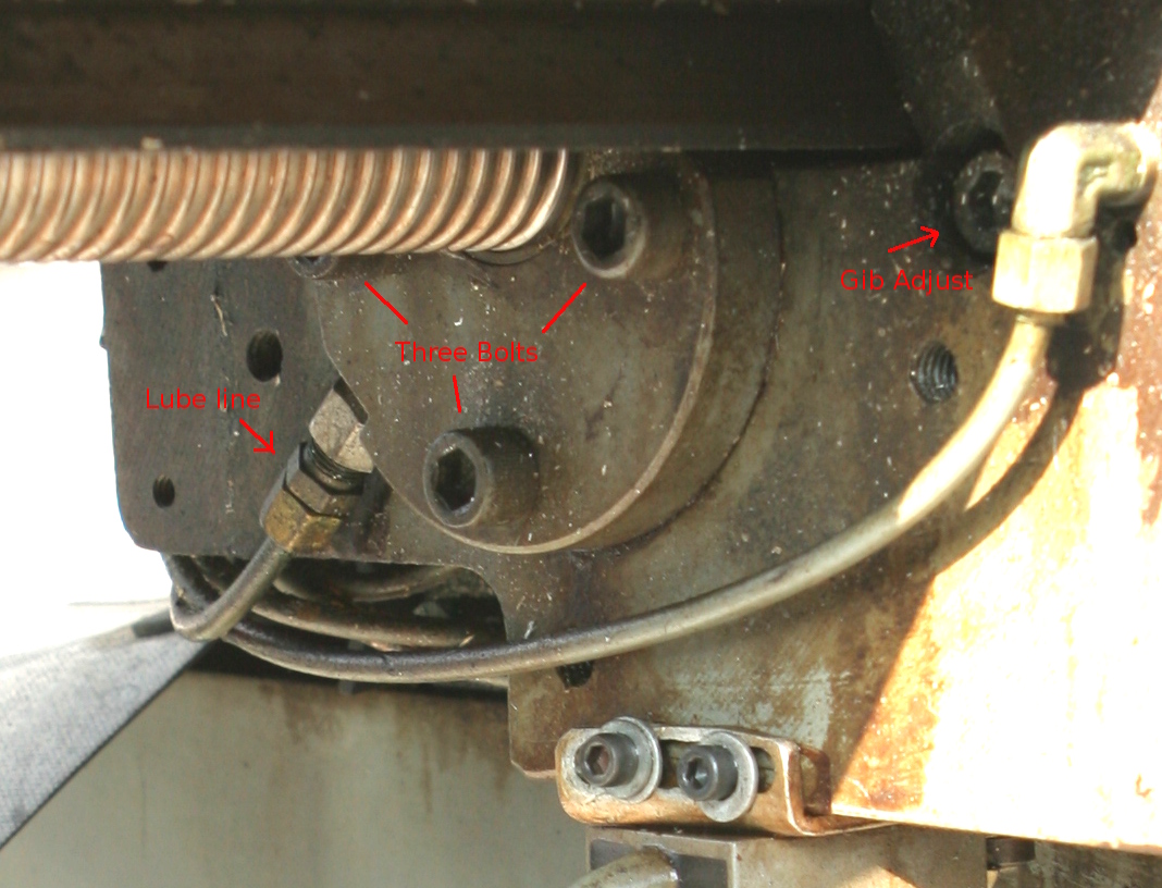
Ball Screw Traveler and gib
Click to see details
Remove the gib adjustment screws on both end of the gib and then
slide the gib out to the left.
There is also a stop piece on the bottom of the far right end of
the table that needs to be removed with it's one bolt.
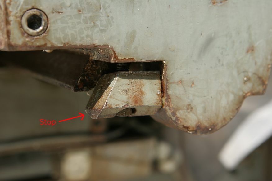
Table Stop
Click to see details
- You may have to remove limit switches.
- Remove the adjusting bolts from both ends of the gib - slide
the gib out to the right - mark the end and orientation before
it is completely out.
- Support the table with bolts in T-slots (make sure they can't
move horizontally). An engine sling and hoist works well to
support the table evenly as you slide it out.
You need to remove the ball screw and table bracket on both ends and
then the gib. . The ball screw can stay assembled with the left side
table and motor bracket assembly. You can then slide the table out
onto a cart
Rebuilding table - really good idea to seal the table so coolants
can't get into the bearings..
Ram (AKA Overarm)
The back to front position of the head and overarm is readily
changed by loosening the 2 hex nuts on the end which clamp the
overarm to the turret. Apply a crank to the overarm
adjustment shaft extension and move to desired position.
Turret
To index the entire turret-overarm-head assembly loosen the 4 inner
hex nuts, 2 on either side of the overarm which clamp the turret to
the top of the column. Then swing
the turret to the desired position and re-clamp. The
complete horizontal spindle, turret, overarm & arbor bearing may
be positioned 30deg either side of normal horizontal milling
position.
NOT E : It is highly recommended that all clamping nuts and bolts
(turret to column, overarm to turret, head side-wise tilt and head
forward-back tilt) be securely tightened before any machining cuts
are taken. Always check these points before starting a cut. Also,
when returning overarm to normal position, attach an indicator to
the overarm, and slide the overarm in and out, with the indicator
riding against a square, which has been squared to front of table to
make sure overarm is square with table. (Why would anyone change
this?)
wiring
http://linuxcnc.org/docs/devel/html/integrator/wiring.html
(BNTECHGO) Or what they call continuous flex cables. (keywords
Continuous-flex Cables high strand count)
Notes for similar
machine
INSTRUCTIONS FOR
CHANGING SPINDLES IN THE FOLLOWING MODELS 745. 747. 756, 757, 845,
847, 856, 857,760, 860, and 887.
- Remove drawbar if it has one.
- Drop knee and move saddle to rear so as to provide clearance
for quill removal.
- Remove (100-027-771) adjustable vernier blade holder.
- Remove two 5/16-18 x 7/8 socket head cap screws in
(100-002-917) quill feed trip key and remove key. Put right hand
on (101 -212-312) spindle feed handle arm and left hand on the
bottom of the quill, and by moving the (101-212-312) handle in a
counter clockwise direction, run the quill down until the rack
on the quill clears the pinion on the cross shaft.
- When this happens, the (101-212-312) hand lever will unwind
very rapidly. If released, it could cause injury. So it must be
unwound slowly.
- Let the quill slide down out of the head casting and put it in
a vise, being sure to use brass or lead jaws in the vise.
- Release the locking ear of the W-07 lock washer in the N -07
locknut or snap ring in the top of the quill and remove nut from
the spindle. (See Paragraph 11) See drawing
- Remove (100-002-972) front bearing retainer from quill after
first releasing the 10/32 socket set screw in the lower rear of
the quill. (NOTE: in the case of #30 MMT, the number is
100002-977.)
- Remove quill from the vise and strike spline or upper end of
spindle against a solid piece of wood laying against a solid
surface, such as the floor. The spindle and the two lower
spindle bearings and spacers will then come out of the quill.
- Replace new spindle and assembly in reverse order making very
sure that the N-07 locknut is tight enough so as to put tension
on the 2968 spacer on serial number before approximately 17105
on R8 spindles and
- approximately 17360 on #9 B & S and #30 MMT spindles.
After this serial number make sure the locknut is tight against
the bearing.
- When putting the quill back into the head casting, first start
the quill into the bore of the casting by gentle pressure and
care (do not force).
- Line up the spline of the spindle with the spline of the
(100-004-576) drive hub by turning the spindle after it goes up
against the bottom of the (100-004-576) hub.
- Next, wind the 101-212-312 counter clockwise to the end of its
spring tension and push quill up until the rack of the quill
engages the pinion of the cross shaft and use (101-212-312) hand
lever to raise quill up to
- the top of its travel.
PROCEDURE FOR
FREEING UP BACK GEAR TO DIRECT DRIVE 745, 756, 760, 845, 856, 747,
757, 860, 847, and 857
This particular problem is usually caused by the (111-218-001)
pulley guard being jolted out of line during shipment and can
usually be remedied as follows:
- Shift the back gear lever into the direct drive (or High) and
set the speed at about 1500 RPM.
- Loosen the eight 1/4-20 x 7/8 socket head cap screws which
hold the (111-218-001) belt guard to the (111-218-212) assembly)
- Turn on the spindle motor, move the (111-218-001) belt guard a
very slight distance in several directions. The dowel pin hole
in the front of the pulley guard can be used with 1/4" allen
wrench to move the pulley
- guard back and forth.
- The pulley guard will actually tend to center itself if
reasonable care is exercised when retightening the eight socket
heads that hold the belt guard to the back gear housing.
Precision limit
switches
They have 3-5um at reasonable prices.
https://www.metrol.co.jp/en/products/
ditron DRO - via Stefan
houdaille taper???
model 3842 -- CEN 701 702 703 752 753 805 ???
lubriquip houdaille cleveland oh
model 120-003-521
timer model 163-400-000
motor IIC Inc MN 55344
30U4-36 S#H 19938
servo motor 2 Milltronic manufacturing
MT30M4-38
jog feed rate
emergencystop
Tool-change resume
feed- hold-pause
###
Stop drill
lockline coolant hose.. 1/4"
FROM TREO
milling machine
servo dynamics corp 15 A module
SD1525-10
B