This information HAS errors and is made available WITHOUT ANY WARRANTY OF ANY KIND and without even the implied warranty of MERCHANTABILITY or FITNESS FOR A PARTICULAR PURPOSE. It is not permissible to be read by anyone who has ever met a lawyer or attorney. Use is confined to Engineers with more than 370 course hours of engineering.
If you see an error contact:
+1(785) 841 3089
inform@xtronics.com
The word analog comes from the Latin analogus, which originated from the Greek análogos, which means proportionate or equivalent to. The electronic use of the word analog is actually very close to the original meaning in that a voltage (or current) changes analogously to something we wish to measure. We use the 'analogy' of a varying electrical voltage (or current) to represent something like a pressure, flow rate, temperature, length, etc.
As an example, we let 0V represent a pressure of 0 PSI and 5V a pressure of 5 PSI then half way would be 2.5V and 2.5PSI. We could also be rather arbitrary and 0V might represent 12PSI and 6.3V could be 60PSI. The economics of reuse dictates that we try to use similar scales. Industry has standardized on a few common signal ranges.
The most common voltage signals in order of their current use are:
0 to 5V (written as 0-5V)
0 to 10V (written as 0-10V)
-10 to 10V (written as -10-10V)
One might also see 1-5V systems, which corresponds to 4-20mA described in the next section.
Voltage signals suffer from a couple of problems, First, the output needs to be rather low impedance and the input high impedance to minimize errors and effects of induced electrical noise. The second problem is if there is any current flowing in the ground connection, it produces a small voltage (E = IR) when flowing through the small resistance of the ground connection. Often, this is reduced by having a separate signal ground that carries no current. Even with the extra signal ground noise can be induced in the wire. This noise can readily detected by the high impedance input. Engineers often resort to shielded wire which works well enough for most applications over especially short distances.
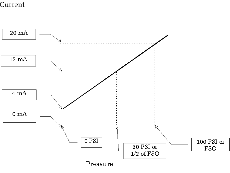
Overcoming the problems of transmitting voltage signals it is common, (and a good choice) to use a current instead of a voltage. The 4-20mA current loop provides a way for both the output and input to have rather low impedance and thus better noise immunity. 4mA represents the minimum and 20mA full scale. The receiving end can detect zero current as a fault (cut wire) condition.
4-20mA current loops also improve reliability as there can never be a difference in voltage between the power supply and the signal during lightning strikes.
| Top Page | wiki Index |
(C) Copyright 1994-2019
All trademarks are the property of their respective owners.