Disclaimer
This information HAS errors and is made available
WITHOUT ANY WARRANTY OF ANY KIND and without even the
implied warranty of MERCHANTABILITY or FITNESS FOR A
PARTICULAR PURPOSE. It is not permissible to be read by
anyone who has ever met a lawyer or attorney. Use is confined to
Engineers with more than 370 course hours of engineering.
If you see an error contact:
+1(785) 841 3089
inform@xtronics.com
Optic equations and
notes
- Disclaimer
- Optic equations and notes
- Diopter or Dioptre
- Focal Length
- Depth of Field
- Contrast Ratio
- Lens power or Magnification
ratio
- Spherometers - lens Radius from
arc depth
- Rayleigh Water Test - for
testing optical flats
- Wavelength of LED or Laser
based on band-gap voltage
- Colors of wave lengths
- Refractive Indexes 632nm
- Coherence time and Length
- Fast Lenses
Diopter or Dioptre
The diopter unit is simply the inverse of the focal length in
meters.

Thus a +2 diopter lens has a focal length of 500mm
You can combine lenses of different diopters arranged in contact
- thus a -2 diopter lens plus a +4 diopter lens would give us the
same 500mm focal length.
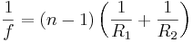
Focal Length
If a lens has surface radii of R1 and R2
and made of glass with an n refractive index the focal length, f,
is defined below
R1 and R2 = surface radii
(negative for convex lens surface)
ng = refractive index of the lens glass
f = focal length of lens
Focal length to angle of view
α = angle of view d = size of film or sensor f = focal
length

Depth of Field
Depth of Field is the minimum to maximum distance in
focus.
Contrast Ratio
Contrast ratio is the difference between the brightest and
darkest point in an image.
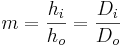
Lens power or
Magnification ratio
Where
m = Magnification ratio or Power
hi = image height
ho = object height
Di = distance from lens to image
Do = distance from lens to object
Spherometers -
lens Radius from arc depth
C of the Triangle is the same as Radius.
The bottom has a calculation of the Spherometers leg from the
radius.
Variables in light optics Greek
V = frequency in hz
ω = radian frequency
δ = path difference (corrected for n)
φ = phase difference
P = order of interference = K
e = thickness
τ = coherence time
l = coherence length
n = index of refraction
a = distance from center
Phase reversal on reflection
Light phase flips (E-field only) when reflecting off a material
with higher refractive index than what it is traveling through.
Brewster angle reflections have no phase change.
If light reflects off an internal wall of a prism or flat - phase
does not reverse.
Phase reversal is important when analyzing coatings.
Rayleigh Water
Test - for testing optical flats
- Monochromatic light source (not LED) - neon/ mercury vapor
sodium
- Leveling platform - fine pitch screws - differential would be
best - but long allen wrench - with long cheater in cap screw
- A lens bigger than the flat - collimator - Fresnel a good bet.
- Black tray - should not rest on bottom of tray?
- Draft preventer - Coraplast taped together
- stable surface - no vibrations - Concrete - add weight to
platform
- LASER pointer
- Magnifier might help see small bands.
- Best water thickness over glass - .9mm± .2mm - A dime is
a bit too thick - but will get you close..

The interference creating bands happens between the water surface
and the top of the glass.
Back to the water test - I'm still not seeing what I want to -
I've started experimenting - trying to see a pattern with a single
microscope slide - the reflection from the front and rear surface
seems close to the water test. (The double slide glass
interference is easy).
To see the single glass, the light and eye want to be very close
together - a normal view point to the surface - It
Getting things level is the hardest bit - point a LASER pointer
straight down - align the dots - and hope you get close. The LASER
should be directly above and aimed so the dots are close to the
LASER - 10mm or less.
The drill is to look without the collimating lens in place - you
want to find rings - adjust so they are wide.. If the rings are
close - a magnifying glass might help. Focus on the image of
the lamp - that is where you will see the first lines. (This
didn't seem to work well - very careful LASER alignment was more
important).
The leveling screws I used were differential - made from a
M8-1.25 capscrew that was drilled out to mount a M6-1.0 -
the thread difference gives 250um per turn.
Fringes formed from a non uniform film (wedge) are called Fizeau
fringes.
Newton rings are a type of Fizeau fringe - the wedge being
concentric from being pressed together at a point.
Haidinger fringes are fringes of equal inclination - pin hole
source best viewed with a large aperture lens. (longer path length
means coherence length is critical).
Wavelength of LED
or Laser based on band-gap voltage
The wave-length in lens specifications is 632.8nm - helium-neon
LASER - (Comes from a persistent neon line --
with low concentrations of a particular element relative to other
substances in the source, the number of observable lines decrease
with decreasing concentration until only the most persistent remain.
Should
have been called a Neon-Helium LASER) but other monochrome light
sources are available - LEDs and LED LASERs
Below is an estimation based on the voltage drop which is close
to the band gap of a forward biased diode.
l = wave length in nm
Eg = band-gap voltage
then

Thus those red LEDs with a 1.9V drop run about 652 nm. (GaAs0.6P0.4)
This appears derived from , 
Where:
- h = Plank's Constant = 4.13 x 10⁻¹⁵ eV·s
- c = speed of light = 2.998 x 10⁸ m/s
Colors of wave
lengths
Infrared 710nm and goes down to roughly 2000nm.
The visible range is considered to be roughly 400nm to 710nm.
390nm to 420 is Blue (or Violet),
530nm is green
Mercury e-line = 546.07 nm
589nm - sodium D lines - a doublet - two lines 589.0 and 589.56nm
- coherence length 0.59mm (must be one line) (588.9950 and
589.5924)
600nm to 710nm is considered red.
632.8nm - helium-neon LASER - neon - bandwidth about
0.002 nm compared to LED bandwidth of 24-27nm -
10,000 wider.
Refractive Indexes
632nm
Fused silica 1.457
Fused Quartz 1.46
Zerodur 1.542
Borofloat 1.472
Clearceram-Z 1.54
ULE 1.48
N-BK7 1.51
Water ~ 1.33
Coherence time
and Length
Example of Coherence Length
Sodium vapor lamp yellow "D" line
• λ = 589 nm and line-width 5.1x10¹¹ Hz
• Thus coherence time and length is
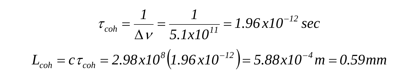
The mercury line at 546.1 is .3mm ?? varies greatly with
tube pressure
Coherence length test
A pen LASER has a coherence length of about 10mm - because the
slide is thinner there is an interference pattern on the
screen. If in place of the slide there was a 15mm optical
parallel - the pattern fails.

Interferometers
Bath Interferometer
The Bath interferometer is not effected by coherence
length. A bit of a puzzle why? The trick is to think
in time - rather than length - thus coherence
time - and to focus on correlation. Light interference requires
the light to be correlated in (average) phase (and to have some
amount of spacial coherence as well).
So for a Newton rings - a type of Fizeau fringe - the time it
takes to travel the two paths - is different - varies in
time. Thus if the source has a short coherence
time - and the difference is greater, the
interference pattern falls apart. When the light arrives - it is
no longer correlated even if at an even cycle time of the given
light frequency.
But for the Bath - the time difference of the path is never
greater than the defects of the mirror under test - those defects
would have to be greater than the coherence length for it to fall
apart. (Imagine a mirror surface with a 10mm defect - the
absurdity makes it memorable <grin>)
The light doesn't care about time varying phase - as long as it is
correlated between the two sources. So if you imagine
that the light source was oscillating in phase like an FM radio
station - limiting the coherence time to part of one of these cycles
- it doesn't matter - the light creating the pattern has the same
phase when it arrives. Coherence time means that phase changes
in time - not because it traveled some length - both beams started
off the same - have the same path length - so will arrive the same
as well. Both arrive highly correlated. So
coherence length matters if the time of flight differs - the key
detail.
The following I think came from Dale Eason - couldn't find the
original link.
Best Practices
The software requires a good “igram” for input – a photograph of the
interference fringes due to interference of the test and reference
beams. These guidelines are meant to supplement Dale’s instructions
with a “Best Practices” for obtaining high quality, clean igrams.
Much of this material is dispersed throughout years of posts in the
messages section.
- XYZ stage - A stable, smoothly controllable xyz stage is
critical to avoid frustration and wasted time in taking igrams.
This can be purchased, for example on ebay, or made (see “A
simple to make Bath and xyz stage” in the Wiki for an example).
Precisely repeatable adjustment as in the wire or caustic test
is not required, just smooth and stable fine adjustment
- Firm foundation - A firm support for the stage and mirror test
stand, such as a concrete slab floor, are also required. A wood
floor generally moves as you shift your weight causing the
fringe pattern to shift. Worst case it may completely disappear
when you move away from the xyz stage after making adjustments.
Also, optical components should be firmly fixed in place, so
they do not move when making stage adjustments.
- Mirror test stand - Using 3 “stops” to define a plane to place
the back of the mirror against in the test stand will facilitate
repeatable positioning of the mirror test session-to-test
session. This works best with two rollers supporting the mirror,
one 45 deg cw (clockwise), the other 45 deg ccw from the bottom
of the mirror, with their axes of rotation parallel to the plane
of the mirror back. No difference in test results was seen
between this type of support and a 'whipple tree' linkage with
rollers at +/- 27 deg from the two 45 degree points for a 22.4"
diameter x 2" thick quartz mirror, i.e. any difference was
within the noise level comparing averages of 30-50 wave-fronts.
A tad of "toe-in" of the rollers helps keep the mirror back
against the 3 support points. The reflected test and reference
beams will then be very close to the same position each time so
that only adjustment of the xyz stage is required to obtain
fringes, with no movement of the tripod or whatever you use to
hold the stage. You can usually find the beams by holding a
screen in front of the flat mirror since they won't be far out
of alignment, and with the above type of test stand support the
only adjustment required will be using the vertical (z) and
horizontal (y) motion of the stage to center the beams, provided
you didn't move the diverging lens or other optical components
from their position during the last measurements. Once aligned
this way, with the reference beam centered on the test beam, you
can then move the camera back, hold the screen there and more
finely adjust so the reference beam covers the test beam. It
typically takes less than two minutes to place the mirror and
adjust the y and z positions (x taken as parallel to the optical
axis) to get good fringes and be ready to take igrams. Some
tweaking of the x position may also be required to adjust the
number of fringes on the mirror. You then of course have to wait
for the mirror to equilibrate in temperature.
- Bath to test mirror distance - A diverging lens position
just inside the test mirror radius of curvature generally works
well. The two beams generally come to focus somewhere inside the
beam splitter. You can fasten a wood block or similar on your
mirror test stand aligned below the mirror center, then run a
tape measure from it to the Bath lens to check distance. Usually
the Bath is mounted on a tripod for rough vertical adjustment.
Move the tripod for initial rough set up of the Bath-to-test
mirror distance.
- Alignment of beams - The test and reference beams should be
approximately parallel to each other. This can be done anywhere
using a piece of cardboard for a screen. The screen can be
placed much further away than the mirror will be during testing
to aid in good alignment. The diverging lens is moved aside when
aligning the beams.
- Beam separation - The distance between the two beam paths
results in some field astigmatism (a property of the surface
being tested). Place the flat mirror so it is almost touching
the bs in a right angle Bath so that you can position the
reference beam on it with less than ~ 8 mm spacing from the test
beam, to minimize Bath-induced astigmatism. The main limitation
on beam spacing will be the cross section of the beams which
determines how close you can place them to the corner of the
cube splitter on a right angle Bath. This also effects how large
a lens you require to be able to relatively easily get both
beams fully captured by it. A 6mm diameter lens was originally
recommended, but it can be difficult to get both beams aligned
in a 6mm lens. Up to 8 mm diameter seems to work fine on most
mirrors, even 9mm. DFTFringe can estimate the Bath and test
stand-induced astigmatism, and testing the mirror at different
rotation angles and averaging the results removes this source of
astigmatism. See Notes about Bath interferometer in the Wiki for
a discussion of Bath astigmatism. Note that not uniform air
density in the optical path can also induce astigmatism, so
always rotate the mirror and test again to see if the
astigmatism is in the mirror or due to air density distribution.
The latter can sometimes be quite a problem, see below.
- Position of diverging lens - After aligning the beams
the diverging lens must be adjusted so the test and reference
beams pass through its center. Misalignment can result in
non-uniform illumination of the test and/or reference beam
resulting in high unwrap errors and wave front distortion. Then
hold a white screen where the camera normally will be, and
observe the test and reference beams and adjust the diverging
lens position until the test beam image of the mirror is round,
and it and the reference beam are both uniformly illuminated.
This is critical for good igrams.
- Laser wavelength - Laser wavelength should be measured for
more accurate results. A number of people have described using a
diffraction grating for this. An example is given in the Wiki
section Measuring laser wavelength.
- Rotating the laser - The laser beam is usually polarized so
rotating the beam (electric field) changes reflection at optical
surfaces and effects the splitting by the beam splitter (BS).
Rotate the laser to determine what angle gives the most uniform
beam and highest contrast in the fringe pattern by observing the
fringes through the camera as you rotate.
- Test and/or reference beam inhomogeneities - The laser diode
beam can have dark areas or “spots”, or “mottling” which can
cause unwrap errors and result in large spikes in the
wave-front. Expanding the laser diode beam by placing the diode
at the focal point of a collimating lens and placing a 2mm to
4mm hole in front of, and centered on the lens can greatly
improve beam homogeneity. The laser diode lens (if any) is
removed in this case. This also generally results in a large,
round reference beam, 2 to 3 times larger than the test beam
when viewed on a screen. This greatly facilitates slight
misalignment of the beams (“tilting”) to adjust the number of
fringes across the mirror image without getting the mirror test
image partly in a darker area of the test beam. This is more
likely to occur with an unexpanded, elliptical or “rectangular”
test beam and may result in such high unwrap errors that the
igrams are useless.
- Many times mottled areas are just due to dust on the optics.
It is important to keep all optical surfaces clean to avoid dark
spots on igrams. Eyeglass lens cleaner and cloths work well. You
can simply slide a plastic bag over the Bath to keep dust off
when not in use.
- Spurious fringes (fringes caused by reflections from the
optical surfaces) - Antireflective (AR) coating of the
diverging lens and the beam splitter (bs) can greatly reduce or
eliminate these. They can be quite distinct with uncoated
optics, resulting in very high unwrap errors – 3k to 7k and
useless wave fronts. They can sometimes be moved off to
the side enough to get usable igrams by rotating the bs a bit,
but this may not be possible. If you rotate the bs, remember you
have to re-align the beams. Rotating the interference fringe
pattern so the fringes are about normal (perpendicular) to the
spurious fringes can significantly reduce unwrap errors, but
they may still be greater than 1k to 2k.
- Fringe print through - The fringe pattern may sometimes be
seen in the wave front as a series of ridges in the shape of the
fringes. Usually reducing igram brightness will reduce these
(say reducing exposure from 1/80 sec to 1/100 sec depending on
your camera/lens and laser diode power). Fringes should be just
bright enough for you to see the edges to place the mirror
outline. Taking igrams at two different fringe orientations on
the mirror will usually eliminate fringe print through.
- Distortion due to air currents and/or stratification - A
tunnel generally reduces air currents, reducing distortion of
wave fronts. A heavy fabric like canvas, or a rigid material
like a cardboard concrete form that resists movement aids in
this. Running a fan to homogenize air in the tunnel can
reduce air stratification, greatly improving wave front
smoothness. Run it for just 20 seconds or so to homogenize the
air, wait a about 10 seconds or so (at around 80 F) for the air
to settle a bit, then start taking igrams. The colder the air
the longer it takes for it to settle.
- Testing in cold air, special considerations A tunnel is
essential to minimize air currents due to thermal mismatch
between nearby surfaces and the cold air. Long times are
required for the mirror to come to thermal equilibrium. A fan
cooling the mirror will greatly reduce this time, but it may
still take several hours depending on the difference in
temperature of your mirror figuring area and the test area. It
has been observed that wave fronts obtained after about 3 hours
may differ a bit from ones taken the following morning, with the
center generally shorter compared to the edge in the wave fronts
obtained after 3 hours. Again, depending on temperature
difference in figuring and testing areas. If testing in
cold air, minimize the time you are close to the tunnel entrance
because air warmed by your body will move into the tunnel
causing air stratification and distortion of wave fronts. When
testing in cold air, difference in floor temperature and air
temperature drives air currents, making it almost impossible to
obtain undistorted wave fronts. Covering the floor area inside
the tunnel with foam or other insulating material will greatly
reduce this effect.
Fast Lenses
Translated from French http://www.dg77.net/photo/tech/fast.htm
to add post it here!
Numerical Aperture

Email
