Your Balplan Microscope will be equipped with one of the following Illuminators:
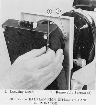
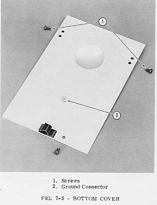
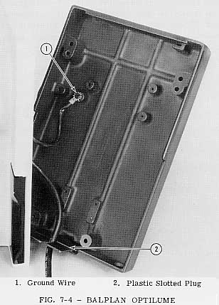
Depending on the type of Illuminator ordered with your Balplan Microscope, it will have either a Base with built-inIlluminator (No. 1 or No. 2 above), or just the Stand with four Neoprene Feet and a Bottom Cover with No. 3 or No. 4 above. The Bases with the built-in Illuminators may be removed by removing the three screws from the bottom, Fig. 7-1, if necessary for installing a different Illuminator. The Bottom Cover may be removed by removing the three screws, Fig. 7-3. If your Microscope is equipped with the Optilume, disconnect the cord from the line supply, and disconnect the ground wire. Fig. 7-4.
The Base Illuminator provides high intensity Koehler Illumination which is achieved through the use of a low voltage lamp combined with a high speed Lens Condensing System, and a Field Iris Diaphragm. A Flip-In 1.0 Neutral Density Filter is built into the Illuminator, and 2" round or square filters may be inserted in the top of the Illuminator.
When ordered with the Microscope, the Illuminator is fastened in position within the Base. When the Illuminator is ordered as a separate item it is necessary to install it on the Microscope as follows:
Remove the Base, or Bottom Cover,
whichever your Microscope is equipped with.
The High Intensity Base Illuminator can
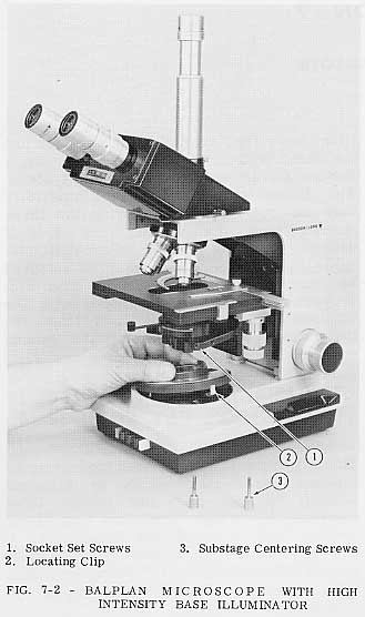
now be installed. The two dowels in the
upper Base ensure the alignment, Fig. 7-1.
The upper portion of the Illuminator snaps
into the upper Base from the top, Fig. 7-2.
The Centering Screws are furnished to replace the socket head set screws shipped with the Microscope, Fig. 7-2. Refer to Field Illumination Control, Section - 2.
A final adjustment of lamp position must be made to ensure maximum performance. Use the 10X Objective and the lowest power Eyepieces available to make this adjustment. Turn on the Illuminator and, looking in the Eyepieces, adjust the position of the lamp filament along the axis of motion (in and out) until the entire field of view is evenly illuminated. Set the stop screw to repeat this position, if desired. Satisfactory results will generally be obtained with all other Objectives by leaving the filament in the initial position. However, to obtain maxi- mum performance for critical observation, it is recommended that the lamp filament position be adjusted for each individual Objective, adjusting the lamp to give the best balance between evenness and brightness.
For maximum lamp life, use the lowest voltage which permits comfortable viewing, reserving the higher voltages for photo- micrography.
To replace a lamp in the Base Illumi- nator, withdraw the Socket Assembly from the rear of the Base by pulling onthe flanged end. Tip the lamp slightly and turn it counterclockwise to release it from the retaining pins. Insert a new lamp, Cat. ^ No. 31-31-42. There is only one lamp position in which the three pins will engage. A partial clockwise turn will lock the lamp in place. Reinsert the unit into the Micro- scope Base. Push forward until it stops against the stop screw.
The Professional Optilume provides variable intensity illumination by the use of a low voltage lamp and a high speed Lens Con- densing System. It has a built-in daylight filter and 2" round or square filters may be inserted in the top of the Illuminator.
——————————— CAUTION ———————————When ordered with the Microscope, the Illuminator is fastened in position within the Base. When the Illuminator is ordered as a separate item, it is necessary to install it on the Microscope as follows:
Remove the Base, or the Bottom Cover, whichever your Microscope is equipped with (see above).
The Professional Optilume can now be
installed. The two dowels in the upper Base
ensure alignment, Pig. 7-1. The upper
portion of the Illuminator fits into the upper
Base from the top.
To replace the lamp in the ProfessionalOptilume, remove the upper portion of the Illuminator by turning" slightly counter- clockwise and lifting. The lamp will then be exposed. Tip the lamp slightly and turn it counterclockwise to release it from the retaining pins. Insert a new lamp. Cat. No. 31-31-85. There is only one lamp position in which the three pins will engage. A partial clockwise turn will lock the lamp in place.
The Optilume is a simple Illuminator with
built-in blue glass filter.
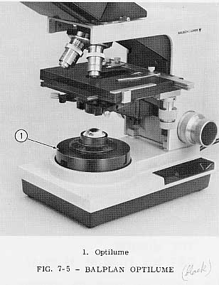
To install the Optilume, remove the Base or the Bottom Cover to give access to the plastic slotted plug in the back of theMicroscope. Feed the power cord through the upper Base and through the slot in the plastic plug. Attach the ground wire to the proper connector, Figs. 7-4, 7-3. Replace the plastic plug. Replace the Base or the bottom cover. Snap the Optilume into the upper Base as shown in Fig. 7-5. Replace the Base or the Bottom Cover.
To replace a lamp in the Optilume, disconnect it from the power source, and remove it from the Microscope Base by twisting counterclockwise and lifting. Un- screw the lamp and replace it with a new one. Use Cat. No. 31-31-12. Reinsert the Optilume into the Base.
NOTE: A ground wire connects the Optilume to the Microscope. Be careful to avoid damaging connections.
The Mirror and mount are available for those who prefer to use an external light source, or for Microscopes using daylight illumination. To attach the Mirror and mount, refer to Section - 1, Preparation for Use.
The side of the Mirror which is used (piano or concave) depends on the type ofillumination and Objective being employed. For general microscopy, the piano side is recommended. However, for low power work, or for work without a Substage Con- denser, the concave side will cover a larger field. For U.V. work and for other critical observations, make use of the First-Surface Mirror, Cat. No. 31-50-67.
The use of Koehler Illumination with an external Illuminator requires the use of a plane Mirror. The light source should be imaged in the Substage Condenser diaphragm plane, and the Lamp Condenser Lens is then imaged in the field of view by focusing the Substage Condenser properly. For the best field coverage, set the Illuminator for the best working distance as specified by the manufacturer. If one is not given, use a distance of about eight inches (Lamp Condenser to Mirror). Focus the Substage Condenser until the Lamp Condenser (or Field Diaphragm adjacent to this Condenser) is in focus on the specimen. Some adjust- ment of the light source or Lamp Condenser may then be necessary to achieve the best uniformity of field illumination. Refer to the Illuminator Reference Manual.