There are several types of Stages available and include:
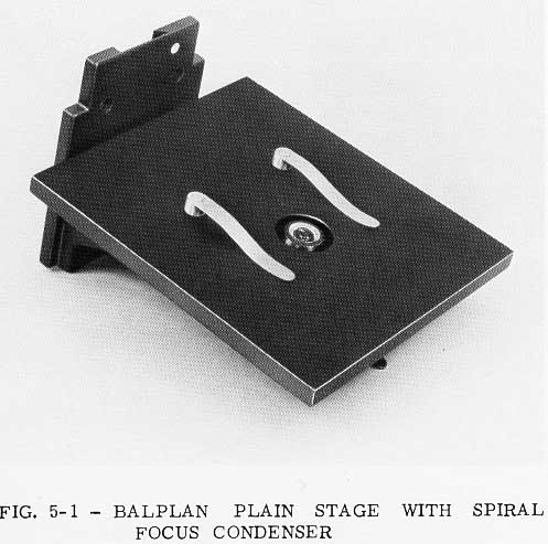
Plain Stage for 31-55-11 Spiral Focus Condenser, Cat. No.31-60-11, Fig.5-1.
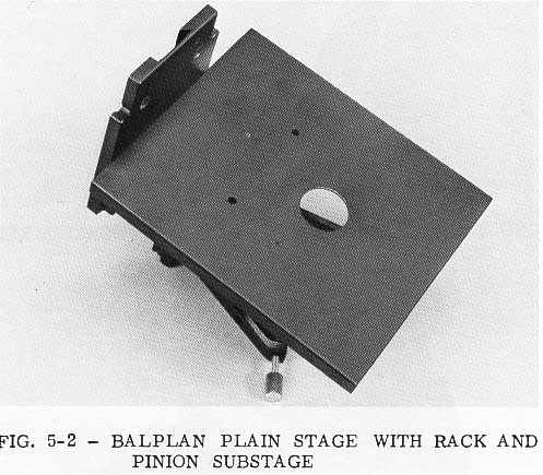
Plain Stage with Rack and Pinion Sub- Stage, Cat. No. 31-60-12, Fig. 5-2.
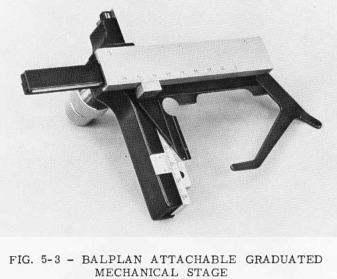
Attachable Graduated Mechanical Stage, Cat. No. 31-60-13, Fig. 5-3.
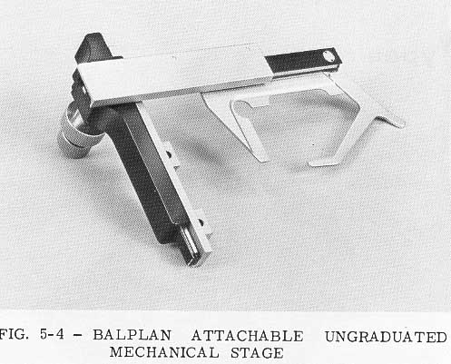
Attachable Ungraduated Mechanical Stage
for use with either Plain Stage, Cat.
No. 31-60-14, Fig. 5-4.
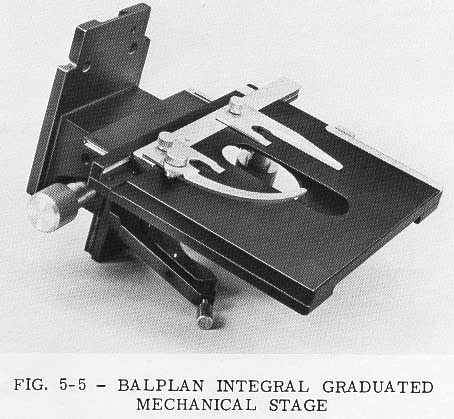
Integral Graduated Mechanical Stage with Rack and Pinion Substage - Right Hand, Cat. No. 31-60-17, Left Hand, Cat. No. 31-60-15, Fig. 5-5.
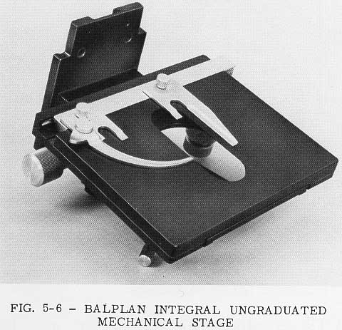
Integral Ungraduated Mechanical Stage with Rack and Pinion Substage. Right Hand, Cat. No. 31-60-18, Left Hand, Cat. No. 31-60-16, Fig. 5-6.
Glide Stage with Rack and Pinion Sub- stage, Cat. No. 31-60-19, Fig. 5-7.
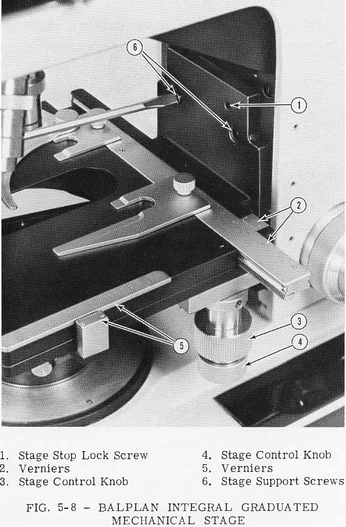
All Stages are interchangeable. To accomplish this, remove the Objectives to eliminate interference. Remove the Condenser and rack the Substage completely upward. Remove the two screws in the face of the Stage Support, Fig. 5-8. Rack the Stage to the bottom of its travel. The Stage may now be lifted vertically.
NOTE: A slight jarring upward may be required to free the Stage from the key. To replace the Stage reverse the procedure. The key will position the Stage correctly. Be sure to replace the two screws in the face of the Stage Support.
Place a glass slide of the thickness which will be most commonly used in position on the Stage below the Objective. Cover the top surface with a thin piece of paper such as lens tissue. Rotate the Nosepiece until the highest power Objective is in viewing position. Loosen the Stage Stop Lock Screw, Fig. 5-8, with the Hexagonal Wrench supplied. Next, raise the Stage to a position that allows the paper-covered slide to contact the Objective. Remove the glass slide and paper. Using the Fine Focus Adjustment, raise the Stage four revolutions of the Fine Focus Knob. Retighten the Stage Stop Lock Screw.
Stage Clips for use with the Plain Stage and Glide Stage are packed in the accessory carton. They should be pressed into the holes provided in the top surface of the Stage.
The Glide Stage may be manipulated in any direction by pushing the entire Stage surface. A special grease-layer bearing on the under surface of the Stage gives a controlled drag motion to the Stage, so that accuracy of control may be maintained. The grease should be cleaned off periodically and replaced with a special Glide Grease, Cat. No. 31-50-04.
 The Integral Mechanical Stages hold the slide in place by a
spring-loaded finger which secures the slide against a Slide Holder
Assembly. The slide motion is con-trolled by the concentric Stage Control
Knobs, Fig. 5-8, on the large vertical shaft. The motion is adequate to
cover a 2" by 3" specimen slide. The verniers on the Graduated Mechanical
Stages are graduated to 1.0mm and permit readings to O.lmm. This
feature makes it possible to record the location of a particular area of
a slide for later reference. Length and separation measurements may also
be made with this device. An unobstructed Stage surface for the hand
scanning of slides with a low power Objective is available by loosening
the knurled screws holding the slide holders to the Stage and removing
the holders from the Stage surface.
The Integral Mechanical Stages hold the slide in place by a
spring-loaded finger which secures the slide against a Slide Holder
Assembly. The slide motion is con-trolled by the concentric Stage Control
Knobs, Fig. 5-8, on the large vertical shaft. The motion is adequate to
cover a 2" by 3" specimen slide. The verniers on the Graduated Mechanical
Stages are graduated to 1.0mm and permit readings to O.lmm. This
feature makes it possible to record the location of a particular area of
a slide for later reference. Length and separation measurements may also
be made with this device. An unobstructed Stage surface for the hand
scanning of slides with a low power Objective is available by loosening
the knurled screws holding the slide holders to the Stage and removing
the holders from the Stage surface.
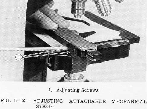
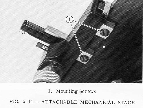
The Mechanical Stage may be attached to either side of the Plain Stage. Two screws are provided with the Mechanical Stage and there are two threaded holes in the underside at each side of the Plain Stage. Place the Mechanical Stage in the desired position with the holes aligned with the threaded holes in the underside of the stage. Insert the screws and tighten securely as shown in Fig. 5-11. If the Mechanical Stage does not operate smoothly, or is not aligned properly, adjust as follows.
Loosen the two screws in Fig. 5-12 about 1/2 turn. This will
leave the upper portion of the Mechanical Stage loose and somewhat free
to shift position. Fold a sheet of paper twice to make four
thicknesses (typewriter paper, or the like, will be satisfactory).
Place this on the Stage surface under the loosened portion of the
Mechanical Stage. Hold the Stage Fingers down against the paper and
tighten both screws. Then remove the paper. This should leave the
Mechanical Stage properly adjusted for most applications. For thin slides repeat the above procedure using less paper.

NOTE: If the Mechanical Stage is attached as in Fig. 5-12, it is preferable to orient the Nosepiece such that the Objectives are pointed away from the Microscope Arm. If the Mechanical Stage is attached to the opposite side of the Plain Stage then the Nosepiece should be oriented such that the Objectives are pointed toward the Arm.
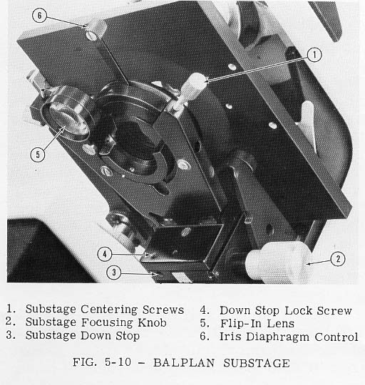
If your Microscope is equipped with a High Intensity Base Illuminator,
Paraboloid Con-denser or Cardiod Condenser, Knurled Head Centering Screws
are supplied for centering the Substage, Fig. 5-10. If your Microscope
includes an Illuminator with no Field Diaphragm, such as the
Professional Optilume or Optilume, the Substage will have been centered
at the factory. Should it be desired to make a slight readjustment,
the Centering Screws may be repositioned by use of the Hexagonal
Wrench supplied with the instrument.
Each Rack and Pinion Substage has an easily adjustable Focusing Stop, Fig. 5-9. This feature is most advantageous when various types of Condensers are to be used on the Microscope. The Focusing Stop should be set so that the Condenser never rises above the Stage surface or contacts the specimen slide. To adjust the Stop, loosen the Focusing Stop Lock Screw, Fig. 5-9, slightly with the Hexagonal Wrench provided. Position the Condenser at the desired maximum height and retighten the Lock Screw. Each Rack and Pinion Substage also has a Down Stop, Fig. 5-10, to prevent interference of various Condensers and Illuminators. To adjust the Stop, loosen the Stop Lock Screw, Fig. 5-10, with the wrench provided. Position the Condenser at the lowest position desired and retighten the Lock Screw.