As microscopes age they are eventually replaced at institutions and corporations when they conclude that more modern microscopes outperform their installed scopes or that the maintenance costs and parts availability have become a problem. When this occurs, these microscopes often find their way into the hands of private owners who cannot afford to have the instruments repaired commercially and must therefore maintain the units themselves. The B&L Balplan now seems to fit this category; having served long and well, these units are being retired and purchased by amateurs -- this monograph attempts to guide the reader through some aspects which experienced instrument technicians take for granted but which might lead the newly minted owner/maintainer to spend time puzzling over how to accomplish common maintenance items.
Disclaimer: This guide is not authorized by anyone (least of all, B&L) nor guaranteed to be correct. It is simply my notes, anecdotes and opinions on techniques and methods for Balplan microscope maintenance which other Balplan owners may find useful. Where known, terminology and names of parts are as found in the B&L manual for continuity. If you find terminology or spelling errors please advise the author.
This is my first attempt at HTML so if you find problems with the presentation, please advise me of that too. As is often the case with hyperlink documents, there are no page numbers: navigation is via hyperlink or scrolling. This document is intended for viewing on a computer rather than as a printout. While my timeless prose is difficult to resist, I'm sure that many readers will simply click on the TOC (above, too) and then on the section of interest, making good use of hyperlinks.
As of December 2005 this work as complete as it is likely to be with only occasional minor changes expected in the future. If you find errors or have a better way of accomplishing a task, please advise the author.
The Balplan is straightforward in design, making it reasonably straightforward to maintain, at least for commonly needed items like cleaning, lubrication, adjustment of stops, etc. More exotic tasks, such as alignment of optics, are not covered in this guide.
The Balplan is a modern modular design which allows constructing a microscope tailored to a specific application by selecting modules and attaching them to a standard Balplan frame. This modular approach facilitates maintenance because the modules from which the microscope is constructed can be easily removed, simplifying access for service.
My scope is a brightfield model so most of the information in this guide pertains to this model. Because all of the models share common assemblies, owners of other Balplan models may also find useful information here. The order of items covered is copied from the B&L user manual where possible to simplify use with those manuals.
Leica was kind enough to supply a photocopy of a Balplan Incident Light user manual which was very helpful in understanding the basic construction and setup of the Balplan (see the appendix for B&L manuals available).
I purchased an old Balplan frame on eBay (most everything removable was gone) but it included the focus mechanism and the drive for the stage. This provided a unit for self-training in maintenance of the focus system and left me a believer in the simplicity and ruggedness of the Balplan. This old frame had apparently been stored in a machine shop since it had many aluminum chips stuck to it (like those from a milling machine). In addition, it had been exposed to the weather so some parts showed rust. A thorough cleaning and lubrication of this old clunker resulted in its coarse and fine focus being smoother than my Balplan (before I put what I learned to use there). I had been reluctant to dismantle my scope without a manual or some experience lest I damage it-- this is where my meager experience was gained. This left me with real respect for the basic design of the Balplan: the fine focus is the item which often makes a scope pleasant to use or not and the Balplan fine focus on this abused old scope was definitely restored to like-new operation with relatively little effort considering the starting point.
A. Installation & Removal
B. Eyepieces
2. Illuminator
A. Removal & Replacement
B. Bulb
C. Collector Assembly
3. Nosepiece and Objectives
A. Removal & Replacement
B. Parfocalizing
C. Lubricating the Turret Track
4. Stage
A. Removal & Replacement
B. Lubrication
C. Adjustments
5. Condenser
A. Removal & Replacement
B. Substage Lubrication
C. Simple Condenser Checks
D. Checking and Setting the Condenser Stop
6. Focus Mechanism
A. Removal & Replacement
B. Lubrication of Coarse & Fine Focus
C. Lubrication of the Stage Drive
Appendix A -- Tools, Gadgets & Lubricants
The heads commonly supplied with the Balplan are:
Binocular, 30 degree #31-18-77
Trinocular, 30 degree #31-18-79 aka Photobinocular
Less common are:
Photobinocular, 30 degree #31-18-14
Binocular, 45 degree #31-18-91
Remove the eyepieces prior to removing the head, this to ensure that they don't fall out of the head when it is moved about after removal. Loosen the clamp screw on the right side of the head. Tilt the right side of the head up slightly and move the head to the left to remove it. Installation is the reverse of removal.
Optics within the head may be accessed for cleaning by removing 4 allen screws to allow removing the eyetube holder assembly. The mirrors are front surface type so great care must be used in cleaning them, in general just sweeping and blowing is needed. I found that the converging lens and the adjacent prism surfaces needed cleaning. Note that adjusting the eyepiece spacing via the calibrated knob moves the parts around internally, facilitating access to the various surfaces for cleaning. If needed, clean and re-grease the spiral grooves in the knob which moves the eye tubes apart.
The eyepieces commonly supplied with the Balplan are:
10x #31-15-61
15x #31-15-62
10x #31-15-67 w/focusing eyelens for use with eyepiece reticles
The most common eyepiece is the 31-15-61 which is a wide field Ramsden design using two lenses. Each lens is composed of two parts which are cemented together. This is a color compensated eyepiece as recognized by the faint yellow rim when you look through it at a fluorescent light. Eyepieces by other makers should work well in the Balplan since as far as I can tell the objective correction is separate from the eyepiece correction; however B&L suggests using their eyepieces. It would be interesting to compare other good eyepieces with the B&L's.
Clean the exterior lenses with brush and blower prior to disassembly. To remove the lenses for cleaning, the top is simply unscrewed. Have a clean, lint free cloth spread out to hold these lenses when they are removed.
A thin thimble is fitted inside the lower end of the B&L eyepiece, visible as slots at the lower end for a spanner wrench (typically not needed here). Remove the thimble by inserting a finger into the bottom of the eyepiece (avoid touching the lower lens) and unscrewing the thimble. A 21mm reticle may be fitted into the recess at the top of the thimble, with the scale on the top, toward the lenses. A spring is not used to hold the reticle in place in this eyepiece; the reticle can be retained by a couple drops of glue or by bending the thin edge of the thimble over the reticle at 3 or 4 points around the circumference - B&L says this can be done with a thumbnail. Insert the thimble with reticle into the eyepiece and screw it into place; view the scale through the eyepiece by pointing it at a fluorescent and screw the thimble in or out slightly to achieve focus of the reticle.
I purchased a 21mm reticle from Cynmar, #012-05275 (the scale seen in some of the photos on my site) for $23. This reticle is slightly smaller than desired so I made a shim from a piece of heavy paper cut to a width slightly less than the thickness of the lens. The shim length was made slightly less than the circumference of the reticle. The reticle was put in place and the shim was placed around the reticle (in the recess) to center the reticle. Several small dots of glue were then put on the edge of the recess to hold the reticle and shim in place. Care must be exercised when cleaning the bottom surface of the reticle since the glue doesn't have much strength, but it works fine this way and doesn't damage the recess as bending would.
The standard illuminators for the Balplan are:
High Intensity Base Illuminator #31-32-16 6v, 20w halogen
Research Base Illuminator #31-32-64 100w or 50w
Incident Fluorescence Illuminator #31-32-66 Mounts below head
The #31-32-16 illuminator includes a field diaphragm to allow Koehler illumination plus a swing-in ND filter to reduce intensity. Color temperature of the illumination may be adjusted using a thumbwheel on the front of the unit. A separate on/off switch is provided.
Cords are commonly missing on used Balplans. These were standard cords years ago but are hard to find and expensive now (Belden still makes them). The simplest solution is to replace the receptacle in the base with one from a dead PC power supply (or purchased at Radio Shack) - this allows using a commonly available computer power cord. Replacing the receptacle isn't difficult but requires some experience using hand tools and soldering.
Remove the head as described earlier. Tape or rubber band a piece of plastic over the opening to prevent dust from entering. Remove the cord by unplugging it from the rear of the illuminator. Remove the bulb holder assembly by pulling it out of the rear of the illuminator. Place a piece of cloth on the bench and tip the frame back onto this cloth to allow it to sit on the back of the frame with the bottom of the illuminator facing you.
Use a 9/64 allen wrench to remove 3 recessed bolts in the bottom of the illuminator which can then be separated from the frame.
In replacing the illuminator, offer the base up to the bottom of the frame and allow the raised bosses near each hex bolt to engage the opposing holes, ensuring alignment (a nice arrangement which makes inserting the bolts easy). Re- install the hex bolts and snug them down. Rotate the frame forward onto the feet and install the bulb holder. Replace the power cord in the socket and you're good to go.
The Bulb in the Brightfield base #31-32-16 is a 6v halogen whose number I believe is: GE 778=20w; the 788 is a second possibility, I don't know which is correct. There are two B&L bulbs: 31-31-81-01 = 778 and 31-31-81-10 = ?; my holder has a sticker with simply 31-31-81. It is a bi-pin bulb with 4mm pin spacing, evacuation via base between pins -- some (wrong) bulbs are evacuated at the top, where the light output is needed with this illuminator.
To change the bulb, remove the bulb holder from the rear of the illuminator by simply pulling it out; the bulb will be seen at the internal end of this assembly.
Never touch a good halogen bulb with bare fingers (if the bulb is hot you won't need a second warning). If the bulb is cold you will deposit finger oil on the bulb and if the bulb is turned on without being washed then the oil will oxidize and leave a minute black area which will forever run hot and eventually cause premature failure of the bulb.
Install a new bulb while wearing gloves and holding the bulb in a piece of clean paper towel. After installation, wipe the bulb with alcohol and then ensure that no cotton fibers are adhering by sweeping with the camel hair brush and/or a lens tissue. Treat the bulb like the optical surface which it is: never touch it and clean carefully. The bulb is tougher than most optical surfaces so you can rub it with a lens tissue.
Temporarily set the frame onto the illuminator. Orient the bulb holder and re-insert it into the base. Ensure the bulb works, then focus the 10x objective and set the field iris and condenser for Kohler. Verify that the field is evenly illuminated. If it is not, try moving the bulb holder mechanism out slightly; if this fixes it, remove the frame from the illuminator base and adjust the stop.
If the illumination can't be made even by pulling the bulb assembly out slightly the assembly may need to be moved in slightly. To allow this, remove the illuminator base (see above) and loosen the stop screw 1 turn, set the scope onto the base, insert the bulb assembly until it contacts the stop and repeat the above. If you don't get even illumination in 2 iterations you have a problem which is beyond my current level of expertise.
If the screw holding the stop is loose in its hole, a drop of glue or paint may be needed to ensure it stays put. Once you're happy with the illumination, re-assemble the illuminator to the scope and re-install the bulb holder into the base.
The collector assembly (my name for it) includes the collector lens, field diaphragm, 45-degree mirror, and a swing-in ground glass or ND filter. The collector lens seems to be a thick aspheric whose flat surface is ground so that it acts as a diffuser (simpler than a separate ground glass diffuser) for the adjacent bulb.
The collector assembly is removable by taking out the 3 screws which hold it to the illuminator base. Ensure the swing-in lens is in the closed position; this lens should be secured in its frame with glue but on my scope it was loose and could drop out if the assembly were inverted with the lens swung out.
The collector lens is held in with an optical ring which requires a spanner for removal. To clean this lens it is simpler to separate the section which holds the lens from the overall collector assembly; it is held to the assembly by 2 screws. Once removed, the lens can be carefully cleaned in place although it is very thick and thus it is awkward to access the sides of the lens near the base.
Once the collector lens section is removed from the collector assembly the field iris is visible for inspection. The iris is operated by a small plastic gear which protrudes upward through a slot in the scope base when the illuminator is in place. This gear drives a barrel which in turn operates the iris leaves. If it is necessary to access the shutter, remove the gear; watch for a thrust washer (between the gear and the housing) which can drop out when the shaft holding the gear is removed. After removing the gear the barrel can be lifted out, keeping the axis of the barrel near vertical to ensure the iris leaves stay in place.
The iris leaves are blued steel with brass pivots. Irises generally are not lubricated with grease or oil since it tends to attract and hold dirt. If needed, a dry lubricant such as graphite or Elmers Slide-All can be applied in very small quantities to the pivots and to the slots in the barrel end which engage the pivots. Clean the outside of the barrel as needed since this may have grease on it (mine did but I didn't re-grease, I applied Slide-All instead).
Removing and replacing the leaves of the shutter is not difficult but it is tedious so avoid jostling the leaves out of place. If they are displaced expect about 15 minutes of careful work using a hemostat to get them back in place. Avoid touching the leaves with bare fingers since salts from your hands may promote rust on the steel.
To re-install the barrel, first push the leaves to the fully retracted position. Gently lower the barrel into place, jiggling it slightly to get the pivot pins to engage the slots. Then put the thrust washer in place over the hole for the gear shaft, put the gear in place and insert the shaft. Tighten gently until the wide part of the shaft contacts the washer (which it always does because the washer works its way off center), use a jeweler's screwdriver to push the washer toward center, tighten the shaft a bit more, and repeat until the washer works its way onto the shaft and the shaft can be tightened with the washer loose on the shaft -- easy after you've done it a couple of times. This is one area where assembly isn't simply the reverse of disassembly....
The 45 degree front-surface mirror can be cleaned in place, see the appendix on lens cleaning procedure. The mirror can be aligned by adjusting the 3 mounting screws -- I don't know how to confirm correct alignment if these are moved so I leave them alone. (Anyone with a Balplan alignment procedure should chime in here).
The swing-in ground glass or ND filter cannot be removed unless the mirror is removed first so it must be cleaned in place also. This is easily done in the swung out position. The mounting bolt is pressed in place so it is easy to adjust the friction of the pivot by adjusting the retaining nut slightly which compresses a spring washer.
Re-assembly of the collector assembly is easy if you put the collector lens section on right side up... Then place it into the base and bolt it in place. You can set the scope onto the base for trial but remember to replace the hex bolts to secure the illuminator to the scope base once you're happy with its operation.
There are several nosepieces possible with the Balplan. Unfortunately, the catalog I have lists nosepiece/lens combinations so I cannot list all of the nosepiece part numbers. The basic nosepieces are:
3 position #31-18-66
4 position #31-18-67
4 position, adjustable centering
5 position
The nosepiece is optically centered by 3 allen screws; two of these are set at the factory and should not be disturbed. The third allen screw is the one which allows removal of the nosepiece.
To remove the nosepiece without removing the objectives, move the stage to the lowest position possible to give clearance to the objectives. Rotate the shortest objective into position, again to give clearance. Support the nosepiece with one hand and loosen the allen screw on the left side of the frame (accessible through a small hole in the frame) about 2.5 turns to release the nosepiece. The nosepiece can be moved straight down until it clears the frame, then moved carefully away from the frame. Alternatively, remove the objectives before removing the nosepiece assembly.
When installing the 3 and 4 objective (non-centerable) nosepieces they may be positioned with the objectives toward the back if desired. Insert the retaining piece into the frame oriented approximately front or rear, holding it firmly upward to seat the shoulder. Slowly tighten the retaining allen screw until it lightly contacts it, rotate the retaining piece back and forth slightly until you feel the allen screw drop into the dimple from the last time it was tightened, then snug the retaining allen screw (this doesn't need to be very tight, over tightening could affect the optical centering). Note that exact alignment on the fore/aft axis is not critical since it will not affect the optical alignment. The 4 objective centerable and 5 objective nosepieces may also be set in the rear position but require nosepiece adapter #31-18-71 to allow this.
The 40x and 100x objectives provide parfocalizing adjustments. Unfortunately, my scope still needed parfocalizing shims under some of the objectives to achieve the desired result; it is hard to say whether this is typical since I only have one sample. It may be easier to access the parfocalizing adjustments if the nosepiece is installed with the objectives toward the back, which is often possible as noted earlier.
To begin, compare the 4x and 10x objectives to determine whether one focuses lower than the other by more than, say, 1/5 turn of the fine focus. If so then determine which and by how much. This is done by focusing with the lower focusing lens on a test slide (diatoms, etc), noting the position of the fine focus knob using the engraved numbers, switch to the other objective and re-focus, noting the numbers on the knob corresponding to the new position. (If more than one revolution is needed, then add 100 per revolution). The difference in position is the thickness of the required shim, in microns. To convert to mils, divide by 25.4. You can purchase plastic parfocalizing shims (marked in mils) or make your own from paper or plastic using a compass with a point instead of a pencil, assuming you have a dial caliper or micrometer to measure the thickness of the stock you choose. Since purchased shims come in 1 mil increments, the result can be 1/8 to 1/4 turn of the fine focus from perfectly parfocal --tightening the objective more or less can help in fine tweaking when a shim is used
Don't spend too much time with the 4x vs 10x initially, just get them close. I found that my 100x parfocalizing adjustment's range was too high and had to lower the 10x by an extra 2 mils to get a match. So, once you get the 10x approximately parfocal with the 4x, a trial of the adjustment range for the 40x and 100x may be a good idea.
Focus the 10x on a feature on the test slide and VERY carefully rotate the 40x into position, watching from the side to ensure it doesn't contact the test slide. To adjust the 40x objective for parfocal, use a 0.035 allen wrench to loosen the parfocalizing lock on the objective. Carefully adjust the parfocalizing screw using a jeweler's screwdriver while watching the test slide. The lock screw may move the adjustment slightly when it is tightened - I found that keeping a light drag on the adjusting screw via the lock screw helps to minimize this effect but it takes a couple of tries to get it right. The adjusting screw is very sensitive so move it very little and very slowly. (The adjusting screw seems to turn a cam which sets the lower limit of the movement allowed on the spring retractable 40x and 100x objectives.)
The procedure for the 100x is similar to that for the 40x. The main difference is that the clearance to the coverslip is even less so more care is required.
After adjusting the 40x and/or 100x to parfocal, it is best to check the stage stop to ensure it is set properly.
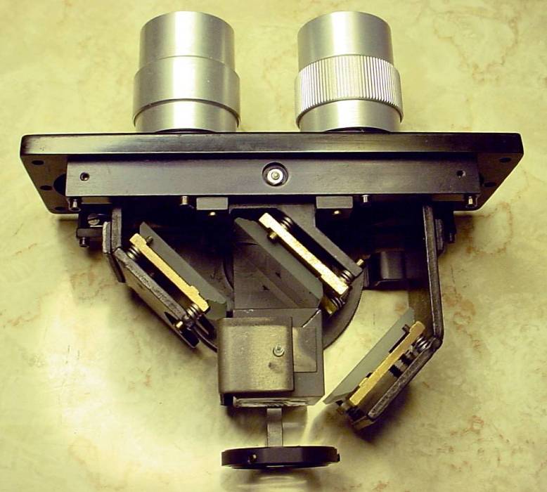
Remove the objectives and place them in a safe, dust-free place. Remove the nosepiece as described earlier. Place the nosepiece on a flat work surface covered with a piece of paper or plastic (such as sheet vinyl) -- this avoids scratching the unit and also minimizes dust. Remove the center screw around which the turret rotates; note the order of the washers and spring which go on this center screw. The turret rotates on ball bearings which run on a track -- when the turret is lifted these balls may stick to the grease and then drop out: use care so they don't make their getaway. In addition, the turret index is another (larger) ball bearing which can be displaced as the turret is lifted so be alert for this too. My approach (per the picture) is to cover the bottom of a pie plate with paper and then disassemble the turret in this plate to ensure no tiny items are lost.
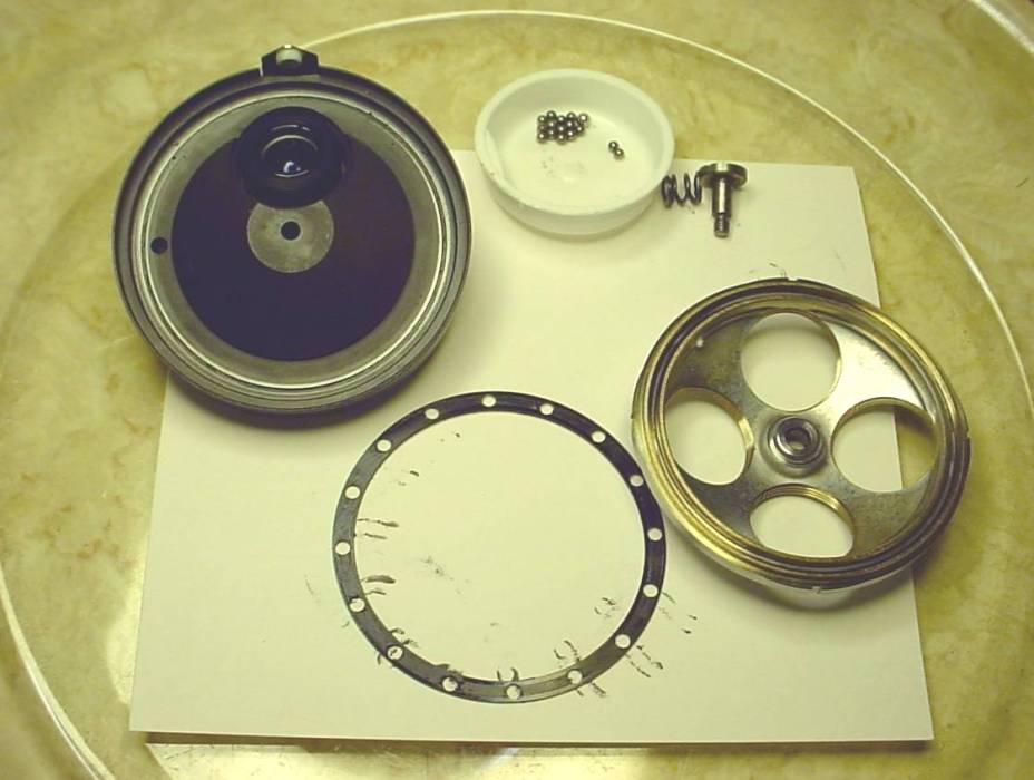
Carefully lift the turret off of its track. The 12 balls will be found in a fiber ring with holes which acts to keep the balls evenly spaced around the track. Lift the fiber ring away from the track, put all of the track balls in a small container, and then wipe grease off of the track, fiber ring, balls, index mechanism, and inside of the turret. Inspect the glass which covers the optical tube; clean if necessary, using care since this is a coated optic lens.
The section which fits into the frame has an opening that normally faces up toward the head. This opening can collect dust and dirt so blow and sweep any dust out of this area. If necessary, clean this lens using the techniques suggested in the appendix.
Apply a small amount of grease to the track, how much is a judgement call. Then, lay the fiber ring onto the track and insert the balls into the holes in the ring.
On my scope, the glue which holds the plastic socket for the index ball had dried up -- this allowed two stable positions for the index, one of which was not parcentric; a dab of contact cement to replace the dried glue fixed it.
Put a small amount of grease into the socket which holds the index ball, then install the index ball into the socket where it will stick due to the grease. Note that the index ball (0.125) is larger than the track balls (0.093) -- don't mix them up. (My scope had one ball of the index size in the track although the index ball was the correct size -- made rotation very noisy and not smooth, took a while to figure out what was wrong...). Add some grease to the track in the turret. Place the turret back onto the track balls where it belongs.
Add a little grease to the washers which go on the turret center screw and re-install the washers, spring and center screw. Snug the center screw down appropriately. Verify that the turret turns and indexes properly.
Re-install the nosepiece as described earlier. Re-install the 10X objective in the position marked with a silver color stick-on dot. Install the other objectives -- in general, such that clockwise rotation of the turret selects the next higher power objective. Check for parfocality, adjust if needed.
There are a large number of stages possible on the Balplan:
31-60-42 Right hand, ungraduated, LH substage controls
31-60-43 Right hand, graduated, LH substage controls
31-60-44 Left hand, ungraduated, RH substage controls
31-60-45 Left hand, graduated, RH substage controls
31-60-27 Plain metallurgical stage
31-60-29 Circular rotating stage
31-60-12 Plain stage with rack and pinion substage
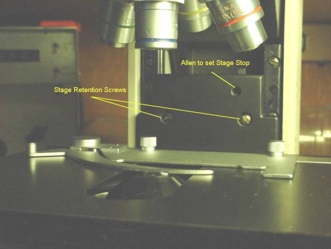
To remove the stage, it is generally best to remove the condenser first simply to ensure it isn't inadvertently damaged. Then, lower the stage to gain access to the two slotted stage retention screws in the vertical plate behind the stage (located about 5/8 inch above the stage). Remove these screws, then carefully lift the stage up slightly and move it forward (toward you) a bit and then to either side to remove it from the frame. It may be safer to remove the objectives to avoid damage when removing the stage -- sometimes the stage sticks a bit so when enough lifting force is applied to overcome friction the stage releases and moves up more than desired. Replacement is the reverse of removal.
Stages with substage x-y controls require little lubrication since the stage is suspended on ball bearings running on stainless. The control shaft may benefit from lubrication but I was unable to dismantle mine: the grey split nut inside the lower knob was removed but the knob itself would not unscrew or pull off so I don't know how this comes apart (anyone?). The knobs were removed as an assembly and light oil was applied to thin the grease which had solidified around the pinion gear shafts; the assembly was re-installed. The gear assembly has room around the screws which hold it in place to allow adjusting the clearance to the x and y racks. This takes a bit of trial and error but it is possible to get smooth operation with no looseness in the movement noticeable via the knobs. As usual, the rack may have a dry lubricant applied (Elmer's Slide-All). This may also be applied to the ball tracks since it doesn't attract dirt.
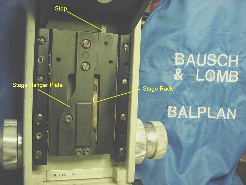
When installing the stage, it is automatically held at the proper height so the retaining screws may be installed. This height is set by a large slotted screw on the back of the plate; unfortunately, if this height needs adjustment it is difficult to do because the screw seems to have Locktite applied.
Verify the operation of the stage stop which prevents the 100x objective from contacting a normal thickness slide by carefully attempting to focus a test slide with the 100x objective. If focus can be achieved, the stop is low enough. Carefully attempt to lower the 100x objective closer to the stage than needed to achieve focus; if the objective approaches closer than is desirable, stop at the desired clearance. Insert a 1/16 allen wrench into the allen screw located about 1/2 inch above the RH stage retention screw, loosen the screw to allow the spring loaded stop to extend, then re-tighten the allen screw.
Alternatively, if focus cannot be achieved due to contacting the stop, lower the stage until you can get your finger over the stop (located on the right just above the allen screw), put your finger on the stop, loosen the allen screw, push the stop down slightly, and tighten the allen screw. Then, follow the above procedure to set the stop.
The B&L procedure is much different: place a slide of the commonly used thickness on the stage and cover it with a lens tissue. Select the highest power objective, loosen the allen which sets the stage stop. Raise the stage until the objective touches the tissue covered slide. Remove the slide and rotate the fine focus 4 turns in the direction which raises the stage. Tighten the allen screw which locks the stage stop.
The standard condensers on the Balplan are:
3-Element Aplanatic #31-55-13 1.25 NA
Flip-in Auxiliary Lens #31-55-14 Used with 4x objective
4-Element Aplanatic #31-55-15 Used with 2.5x objective, has flip out hemisphere lens
The dark field condensers for the Balplan are:
Paraboloid #31-55-33 1.20 to 1.37 NA
Cardioid #31-55-33 1.20 to 1.39 NA
To remove the condenser, rack the substage down to the stop. Grip the condenser at its widest point (using both hands) and pull it toward you. The condenser is retained by a spring loaded plunger which grips a cam on the rear of the condenser assembly so it should pop out easily. (I found that the pull required on my scope was higher than I wanted so I shortened the spring to unload the plunger a bit.)
Remove the stage as described above. Remove the knob which focuses the condenser using a 1/16 allen wrench. Remove the barrel which surounds the focus shaft -- you may need to make a tool to do this since the shaft is in the middle of the slot. Clean dried grease from the shaft using WD-40 if needed. Re-grease the shaft and re-install the barrel and the knob.
Lower the condenser stage and clean grease and dirt from the rails. Apply a small amount of grease to each rail and run the stage up and down. Wipe away any excess grease. The friction of the condenser stage can be adjusted via the two phillips screws accessible from the right side.
Clean the rack and pinion gear which drives the condenser stage, then spray them with Slide-All.
If the plunger needs lubrication, remove the 1/8 retaining allen screw. Remove the spring and plunger, clean and re-grease, adding a little oil if needed to thin the grease. I shortened the spring a bit to make it easier to remove the condenser. Assembly is the reverse of disassembly.
Re-install the stage and condenser as described above.
Adjust the drag on condenser movement by tightening or loosening the two slotted screws accessible from the right side of the substage. These screws adjust the pressure on the mounting rails; they are sensitive, but not difficult, to adjust.
Center the condenser using the adjustments provided and move it to the upper stop. Open both the field iris and the condenser iris. Select the 4x objective and flip out the auxiliary condenser lens. Place a slide with upper side frosted (directions for frosting a slide) on the stage. Focus the frosted surface with the objective: this will leave the edge of the field iris visible as a circle of about 1/2 of the visible diameter. Adjust the condenser to focus the field iris image as is done in setting up Kohler illumination. Check the edge of the field iris for color all the way around as you move through the focus point. The color should match, i.e. it should be red all the way around and then turn blue all the way around as you pass through condenser focus. Try this with the field iris open all the way and open about half way. If it consistently does not transition color evenly it may mean that the condenser is at a slight angle, needing correction via shims, etc. Try a paper shim under one edge or the other of the condenser to determine what is needed. ( I don't know how to fix this since I haven't actually seen it happen. If the the color difference is left vs right, adjusting the stage hanger plate angle slightly may fix it.)
Check the centering of the condenser with the setup above but using the 10x objective, adjust centering as needed. Select the 4x objective as above. Verify the centering by comparing the outside edges of the illuminated circle with the ends of the reticle scale; it should agree within 0.1mm. Close the field iris to its minimum diameter and note the offset from the center of the reticle; again, it should agree within 0.1mm.
Move the flip-in lens into position to fill the 4x field. Close both the field iris and the condenser iris; the small illuminated area should be directly over the center of the reticle. If it is not, try moving the flip-in lens slightly to see if the track the illuminated spot follows appears as if it will pass through the center of the reticle -- if so, try adjusting the allen screw in the handle of the flip-in lens a bit to move the spot to the desired position.
To check the upper condenser stop, remove the slide clamp from the stage. Move the condenser to the upper stop. Place a slide on the stage, over the condenser, and verify that the condenser does not contact the slide. To judge the clearance, use a piece of heavy paper (e.g. a piece of a business card) as a feeler gauge to ensure proper clearance which should be about 15 mils. Replace the slide clamp once you've made the measurement.
To verify that the upper stop will allow proper range, verify that the upper condenser stop allows focusing the edge of the field iris as described in the prior section.
A further check is needed if darkfield operation is anticipated: place a slide with the frosted side up on the stage. Select the 4x (or 10x) objective, open the field iris and the condenser iris, flip out the auxiliary lens, then focus on the frosted slide. Center the condenser, then install the largest darkfield stop (typically about 11mm, as used with the 40x objective)and move the condenser down about 1/8 turn. Look at the frosted surface through the low power objective and verify that you see a dark area. Slowly move the condenser upward and verify that the dark area becomes a dark circle surrounded by light, then the dark circle disappears and is replaced by a bright spot. If the condenser cannot be moved up enough to achieve the bright central spot then the stop may need adjustment (It may be necessary to oil the condenser to the slide, although I have been able to get good results without oil.).
To adjust the condenser stop, loosen the allen accessible from the right side -- this frees the stop pin, allowing the condenser to be positioned as desired. Re-tighten the allen once the desired condenser position is achieved. Verify clearance between the condenser and a slide as described earlier in this section.
The Balplan focus mechanism is elegant in its apparent simplicity and in addition is easily accessed for service.
Removal of the complete focus mechanism requires a spanner which I don't own (yet) so this section is not complete at this time.
Remove the stage to unload the focus mechanism so it won't move under the weight. Remove the rear panel on the frame (by removing the 4 screws in the corners) to expose the fine focus mechanism.
To remove the knobs, slip the tip of an Xacto knife under the edge of the black plastic disk in a fine focus knob and lever the disk up slightly, insert the tip of a pin under the lip where it is raised, get the blade in a bit further, and the plastic should come off; it is held by a stringy rubber cement and can be re-inserted again if you're careful not to get anything on the glue surface while it is out.
Use a 7/16 nutdriver to remove the lock nuts inside the fine focus knobs, holding the associated knob to prevent rotation. Loosen the allen screw in the left knob and unscrew that knob, then do the same for the right (numbered) knob. (The allen screws have nylon inserts between the screw and the shaft so they don't really lock the knob to the shaft -- the lock nuts do that so I don't really know why the allen screws are used.) Keep track of the washers which go with the knobs and their orientation for re-assembly later. The fine focus shaft should now be movable endwise with finger pressure, moving 1/4 inch or more fairly easily.
Remove the nut on the end of the pinion gear shaft, then remove the clutch plate which engages the pin in the end of that shaft. This disconnects the focus mechanism from the stage.
First, expose the focus mechanism for lubrication. Then, with the stage disconnected from the focus drive, evaluate the friction/drag in the coarse focus. If the drag is greater than desired, first clean the grease off the large worm gear which drives the spur gear on the stage drive shaft. Also clean the grease off the spur gear -- these are the large gears which are obvious when the rear panel is removed. Dried grease on these gears is common and adds a lot of drag. The moly grease works well here and may reduce drag -- some brands of scopes apparently need the friction provided by thick grease to prevent "creep" in the focus but I haven't seen this on my Balplan.
Since I haven't got the spanner to remove the focus mechanism, I added oil around the shaft on either side; hard to say if it helped. I expect that there are ball bearings supporting the coarse focus shaft which will be exposed once I get a spanner.
To lubricate the fine focus mechanism, first turn the fine focus (ff) so that the drive gear moves all the way to the left compressing the spring which is located on the shaft. This will expose most of the fine focus thread, visible in the opening in the coarse focus shaft. Wipe as much of the dried grease off of the ff threads as possible using a paper towel and being careful not to leave fibers on the works. I used WD-40 here as a solvent to help get the grease off. Then wind the ff mechanism to the other extreme and clean the other end where it is exposed through the spring -- this is admittedly awkward but it was the best I could do without removing the mechanism. Wind the ff back the other way and clean again.
Tip the frame to one side and apply oil to the ff shaft on the low side where it enters the end near the knob. Spin the shaft to work the oil in so it will thin any grease between the two shafts. Treat the other end similarly, then slide the ff shaft back and forth endwise to work the oil in more and further thin any dried grease. Wipe away any oil which may have run back out of the ends into the coarse focus shaft or onto the outer ends of the ff shaft.
Wind the ff gear all the way left again and apply some of the moly grease to the ff threads. Wind the ff the other way, apply moly through the spring to the threads on the other end, and wind it back and forth a couple of times to spread the grease over the shaft. Wipe any large clumps away but try to leave a good layer on the threads. Wipe a little grease onto the shaft where the ff drive gear slides on it, add a little oil to thin it out and wind the ff end to end a couple of times.
Install the washer and numbered knob onto the right side. Screw the ff knob on while pushing it toward the opposite side; stop when the shoulder on the other side is even with the outside of the coarse focus knob. Tighten the allen screw in this ff knob, then install the locknut and tighten it.
Install the spring washer and left ff knob. Screw the knob on until the end movement possible by pushing on the end of the knob is about 1/16 of an inch -- this is a judgment call which depends on the amount of drag desired on the ff knob. It isn't possible to get a large drag by tightening but it is possible to reduce drag by loosening this tension slightly. Loosening it too much results in excessive end play which could cause shifting in the ff. Once you set the tension, tighten the allen screw and install the lock nut. When all is satisfactory re-install the plastic end disks.
To evaluate the drag in the stage drive, spin the shaft of the stage drive pinion by gripping the end of the shaft where the pin protrudes. Also, try moving the drive plate to which the stage bolts up and down by hand. If the drag is excessive (a judgment call) then lubrication of the shaft can be investigated but is unlikely to make a large difference since it runs in ball bearings. Also consider the rack and pinion gears as a source of drag, especially if the unit is old and may have been exposed to dust or dirt. Check the tracks for dirt also.
Before removing the stage drive shaft or (by implication) the stage hanger plate (my name for it), realize that the hanger plate position affects the condenser alignment. Its removal should only be undertaken if absolutely required and then only after figuring out how you will reproduce the existing vertical alignment when reinstalling it.
Use locking pliers to grip the pin in the drive shaft, then tap the locking pliers lightly with a hammer to remove the pin. Remove the spur gear. Remove the stage hanger plate from the stage drive plate by removing two flat blade screws and 3 allen screws. This allows the removal of the stage drive shaft and its attached pinion gear.
Lubricate the two ball bearings which support the drive shaft using moly, or oil, or a mixture. If any dirt or grease is present on the rack or pinion, clean it off (using WD-40 on a paper towel only if needed). The rack can be removed if necessary but then has to be aligned so avoid removing if possible. Lubricate the rack and pinion with Slide-All and re-install.
I don't believe the stage drive plate can be removed -- it looks as if the track mounting screws are permanently installed and painted over. If necessary, clean and lube the tracks in place. The suspension is by steel balls riding on steel wire tracks so it is unlikely to need much lubrication nor is lubrication likely to decrease friction very much with this design. Removal of grit and dirt from the tracks could make a noticeable improvement. Anyone with better info should chime in here.
Re-install the spur gear and the plastic friction plate onto the shaft and put the pin in place. Use locking pliers to press the pin in place - this may take several increments but it works well. Don't press the pin in farther than necessary; try the clutch plate after each increment and quit once the plate goes on. Re-install the stage hanger plate if it was removed. Re-install the stage to ensure the full weight is in place when setting the clutch friction.
Install the clutch plate and retention nut. Snug the nut only slightly. Set the clutch tension by running the stage drive plate into the upper stop. You should find that the plate can be moved to the stop using the coarse focus, if it can't, tighten the clutch nut slightly -- this adjustment is sensitive so go slowly. When set properly, the plate will move up to the stop without slipping but contact with the stop will not be noticeable through the coarse focus knob. Again, this is a judgment call -- here, if the nut is tightened too little the stage will not move up as needed while if the nut is tightened too much it may be possible to raise the stage with sufficient force to damage an objective through this contact (assuming that the stage doesn't contact the stop).
Test operation of the coarse and fine focus then re-install the back plate.
Since this guide is aimed at amateur Balplan owners, the required tools are minimal and sometimes crude. You may have a better tool or method so feel free to use it and to contribute a suggestion for inclusion here.
Allen wrenches -- one of the folding sets which starts with 0.050 and goes through 5/32 is useful. Actually needed are:
0.035 allen for parfocalizing locks
0.050 allen for focus and fine focus knobs
1/16 allen to remove nosepiece
9/64 allen to remove the illuminator
Screwdrivers -- a set of flat blade jeweler's screwdrivers (Radio Shack or equal) plus regular size flat and Phillips drivers.
Locking pliers and a small hammer (to remove the pin on the stage drive clutch). I told you this was a guide for hammer mechanics :-) .
Nut drivers aka Spintites (like screwdrivers but have hex sockets on end) or a 3/8 deep drive socket set. Mainly, a 7/16 deep socket is needed for the fine focus shaft.
Spanner aka optical spanner wrench. I wish I had one of these, they're useful for opening numerous optical gadgets and also, with the correct tips, for removing the Balplan focus mechanism. They have 2 flat or round blades which can be set an adjustable distance apart, inserted into holes or slots, and used to screw in/out an item like the thimble in the eyepiece or the nut securing the shaft of the focus mechanism.
Microscopes typically use expensive "damping Grease", see <www.micro-tools.com> for a kit of 7 greases for $64. Carolina has 2 greases available on their site (see microscopes/compound/accessories, 2nd page). I have used commonly available greases in most areas with no obvious bad effect, your mileage may very. Grease is used very sparingly so an ounce or two will last a long time.
One caution: non-microscope greases can exude oil which migrates around over time so don't use the cheap stuff where this could occur such that it gets on the optics. The grease you apply today may not be (or need to be) renewed for years so choose your grease accordingly. Fortunately, in the Balplan there are few places that need greasing near the optics. Never apply grease or oil to the objective threads -- if they need lubrication, spray some Slide All onto a plastic surface and scrape a little of the deposited Teflon dust up with a toothpick and apply that to the threads.
Some scope users advise use of silicone grease since it doesn't dry up so it should be permanent. I avoid silicone greases since there is no solvent to aid in their removal -- once it gets onto something there is no easy way to remove it completely. My fear is that I would accidentally touch it and then get some onto an optical surface -- there's no way to remove it without a solvent...
Pennzoil Adhezolith EP fibrous Lithium Grease w/moly (don't you love the name!) from the auto parts store. This is a long fiber black grease which is soft and stringy. I favor moly based lubricants because of their superior performance in most applications but this stuff is messy...
Plumber's Heat-Pruf grease is a very thick grease (from the hardware store) used in faucets which I use as an inexpensive substitute for damping grease. In particular, it seems to work well on the turret ball races.
Elmer's Slide All, a dry lubricant spray. I use this on rack and pinion gears since it doesn't hold dirt -- the pinion gear is exposed in nearly all microscope applications and the Balplan is no exception. For no apparent reason I think this is Teflon dust but Elmer doesn't say that on the can.
10W-30 oil for autos. I use this to thin out grease in places where I'd like lower drag. Alternatively, some Dexron transmission fluid would likely work well since it is a synthetic oil.
WD40 is used as a solvent to remove grease or oil which has dried up in an area where it is difficult to remove. Always wipe WD-40 away after use since it is not a good lubricant.
Camel Hair brush - from the camera store or an artist's brush
Blower, bulb type Radio Shack sells a "solder sucker" or get a blower/brush from a camera store.
Lens tissue, keep in a Zip lock bag to avoid contamination.
Lens cleaner; isopropyl alcohol may be used but real lens cleaner may be better.
Q-tips are useful for lots of things but not the best thing for lenses since they may contain adhesive;
cotton from the drugstore and heavy toothpicks are better.
Exam gloves (non-powdered) from the drugstore. Wear gloves when working on internal optical surfaces since finger oil on lens tissues can be a problem.
Good lighting is critical when cleaning optics.
Blow any loose dirt off, use the camel hair brush, blow again. Decide whether further cleaning is necessary. Application of fluid to objectives is always perilous since some fluids can damage lenses by eroding the lens cement. If you decide to use fluid, use very little on a toothpick/cotton swab (not a Qtip), wipe immediately with a second swab. Remove the resulting lint with the brush and blower. Use a lens tissue if needed. Another helpful technique is to roll a lens tissue around a toothpick, with 1/2 inch or more beyond the end of the toothpick, then use the projecting tissue as a brush or cleaning tool (with fluid if needed) Alternatively, roll two lens tissues together and use the end to clean the lens; cut 1/8 inch or so off the roll to eliminate any dirt removed from the lens and use it again - a simple way to get extended use from lens tissues.
The internal ends of optics often use a softer coating than that used on the external ends so be especially careful with these. A sad story on eBay concerned a very expensive Leitz lens which was damaged by too much fluid applied to the inside surface which seeped into the lens and damaged the cement between the lenses comprising the objective -- the moral: be VERY careful with fluid on objectives. I don't know whether these problems occur with Balplan lenses and certainly don't want to be the one who determines that they do....
Mirrors are particularly difficult to clean because the coating is soft so it scratches easily. Try to limit mirror cleaning to sweeping/blowing. Go VERY gently if fluid is needed.
The final step in lens cleaning is often to exhale on the lens to deposit a fine film of moisture, then polish the surface gently with a lens tissue, always handling lens tissues with exam gloves to avoid oil contamination.
One item often forgotten is cleaning the lens brush itself. Dust and even grease can adhere to the brush over time so you should occasionally clean this brush with alcohol or some other solvent. I use alcohol on used lens tissues to clean the brush which seems adequate.
My Balplan eyepieces were very dirty initially so they were dismantled for cleaning. This was more difficult than expected because oily streaks kept showing up; this is where I learned that exam gloves should be worn when handling lens tissue.
Adding a reticle to the eyepiece was really exasperating because the reticle is in focus so ANY dust or oil is very obvious. It seemed as if the reticle took a static charge since for several days new dust kept arriving, requiring removal and sweeping/blowing. Eventually, it settled down but then some latent oil trapped more dust, requiring fluid cleaner, starting another cycle of sweeping/blowing.
Dismantling an objective is a last resort, taken when all else fails and one decides that commercial repair is more expensive than replacing the objective. The objective dismantled here was supplied to me by Larry Boyd (Thanks Larry) when he aquired a replacement. Disassembly was undertaken as a learning experience to be shared with readers of this guide; repair of the lens was a desirable but not an expected outcome. Unfortunately, the lens was damaged during the experiment. However, knowledge about how to avoid oil in the lens, which caused the original problem, was gained so there was some benefit.
The original difficulty was a degraded image from the 100x objective. Comparison with my 100x showed that the resolution was significantly degraded, enough to make the objective useless although it was possible to achieve a blurry image.
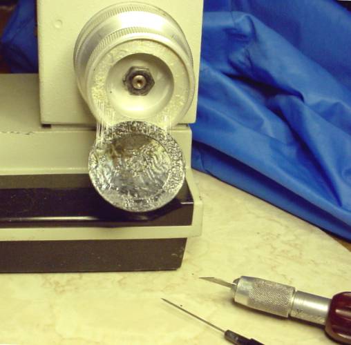
In retrospect, removal of the objective's upper lens will usually be unnecessary so constructing a spanner should be put off until it is determined that it is needed. I initially removed the upper lens using a small spanner which I made from a section of brass (.25 X.060 X 12") from the local hobby shop. The brass was cut to length and #68=0.031 holes were drilled to match the holes in the lens. The center of the brass piece was filed to clear the center part of the lens. Short pieces of 0.025 piano wire were inserted through the drilled holes to complete the spanner - the mismatch between hole and pin accommodates minor errors in wrench construction. As usual when working with small parts, disassembly in a shallow dish helps to keep the parts count stable...
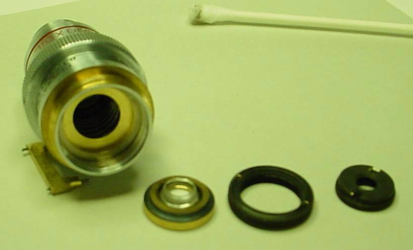
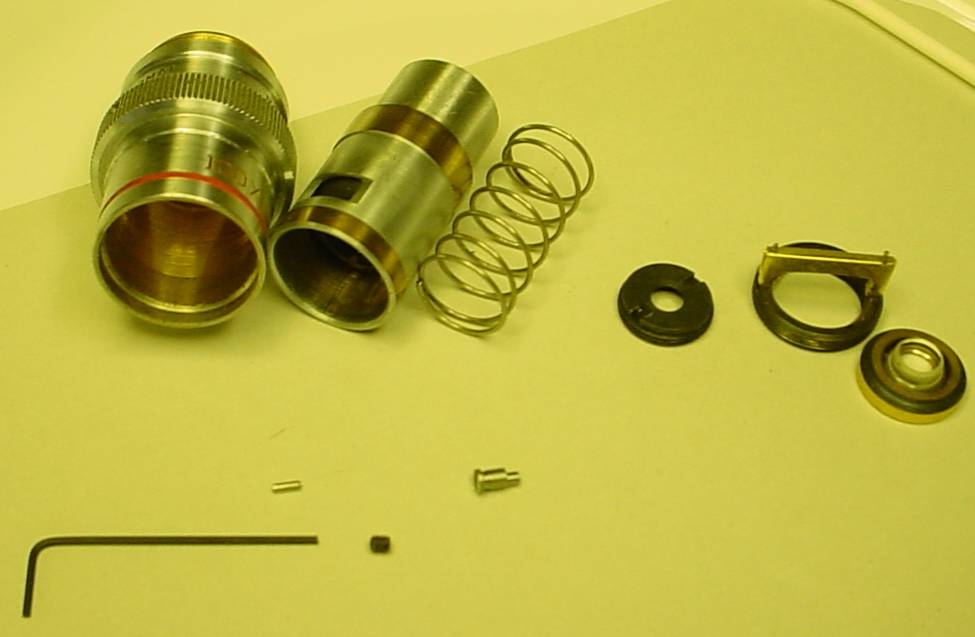
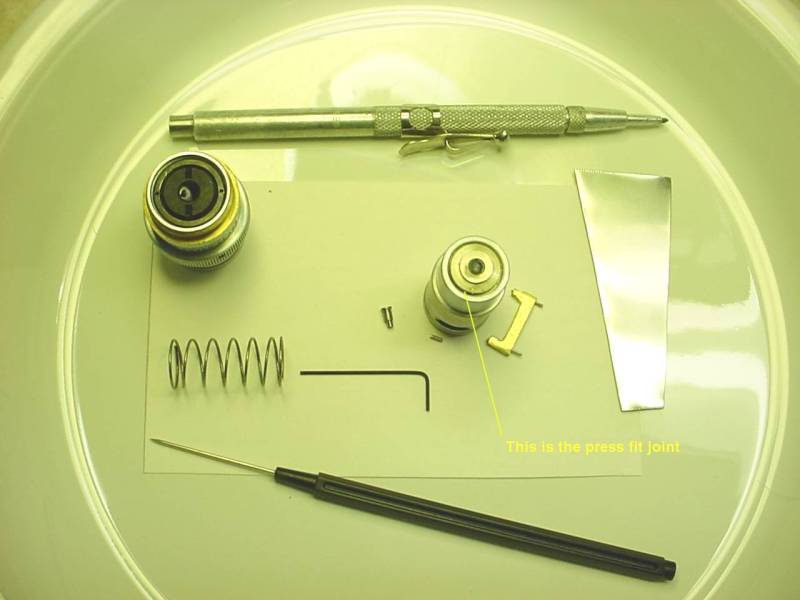
Initial disassembly requires removal of the small roll pin located opposite the parfocalizing adjustment. I pushed this pin in slightly with my carbide scribe (the scribe tip locates in the center of the roll pin nicely) and once it was started, pushed it through with a dissecting pin -- alternatively, a paper clip might work. The roll pin will drop into the barrel so keep the objective axis horizontal until initial disassembly is complete. Rotate the lens to bring the parfocalizing adjustment uppermost, loosen the lock 1 turn with the small allen wrench. Squeeze the objective to compress the spring (which allows the objective to retract when it contacts a slide) slightly, use a magnet to remove the parfocalizing cam, then slowly release the spring. The bottom of the objective is a sliding fit into the top but the spring could cause it to pop out so use caution in separating them. This is the result with the top lens also removed. The picture shows the roll pin and cam, the upper lens removed (with spanner in place) and the lock screw (erroneously) removed.
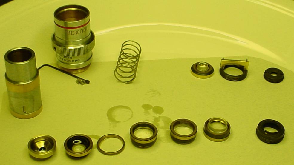
The lenses are retained in the lower barrel by a ring which is removed with a large, thin screwdriver. I made this tool from a scrap of sheet stainless; although soft, it worked just fine since the ring is only snug so little torque is needed to remove it. The individual lenses in the barrel are mounted in brass holders which are stacked in the barrel. These are a snug fit and the outer lens is effectively a press-fit into the barrel. To remove it, use a hollow tube which fits around the projection and inside the barrel seam to push the assembly upwards into the barrel - use care to avoid rapid movement when the assembly releases. This is the result with the lenses removed from the barrel. There was a significant amount of oil between the lenses such that it seemed to fill the voids between the first, second and third lenses; this would suggest that performance probably degraded slowly over a considerable period of time. As part of my initial inspection I looked through the objective while it was off the stand (checking for oil) and it seemed clear; this may be due to inexperience on my part.
I have read that the interior lenses use a more delicate coating than exterior lenses so I was (and still am) unsure of how to clean the oil from the lenses without disolving the cement. I wiped the oil from the brass surfaces with qtips and wicked it away with paper towels, then tried to wipe it off the lenses with the ends of rolled lens tissues. A thin film of oil resisted removal so a solvent of some type is needed but it is hard to say what solvent would neither damage the coating nor disolve the mounting cement...
Eventually, I decided to re-assemble the lens and try it. I placed the lenses into the barrel one at a time and pushed them down using opened tweezers against the outside brass mounting rings. This worked initially and allowed re-assembly, with the threaded ring pushing the lenses down to their normal position. Unfortunately, I mixed up the order of the lenses so I had to remove them again. I noted that oil from the inside of the barrel had been scraped onto the mounting rings as the unit was assembled so I cleaned the inside of the barrel with xylene which seemed to remove the oil completely. However, on re-assembly one of the lenses cocked slightly and seized in the barrel (perhaps this would have occurred sooner without the oil in the barrel); I applied some pressure with my tweezers to move it into place and apparently the uneven pressure flexed the mounting ring, causing 2 small chips at the edge of the lens. On completing re-assembly, the lens works better than it did initially but the result is not acceptable, whether due to the remaining oil or the chips is unknown.
A simple tool, consisting of a short piece of appropriate size tubing set in a small block of wood would simplify disassembly and also allow safe reassembly. The lenses could be stacked in order on this tube and then the barel could be pressed down over the assembly. Alternatively, the lenses could be set on the tube one at a time and inserted into the barrel where friction would retain them. Either approach would likely be an improvement on my technique.
The major thing learned from this experiment (other than don't allow a hammer mechanic near an objective) is that technique is important when oiling the Balplan's 100x. My guess is that the seal around this lens is fine; the oil likely entered via the press-fit joint between the outer lens and the barrel. By using care to avoid oil migrating to the press-fit joint and especially oil+solvent one can likely avoid the problem entirely: use oil sparingly, blot it off when done, then wipe carefully to avoid smearing oil onto this joint.
Information on which solvent to use in cleaning internal surfaces of Balplan objectives would be appreciated.
A frosted (ground glass) slide is very useful for testing operation of the illumination system, especially the condenser and its alignment. Choose a standard 1mm (39mil) thick slide to frost.
To make some fine grinding compound, place a few tablespoons of fine sand in a tall plastic bottle with water, shake, wait for 30 seconds or more, and pour 3/4 of the water into a second container -- the suspended material will be the fine part, the coarse will have settled to the bottom. Discard the coarse sand from the bottom of the bottle and use the fine sand which settles in the second container as grinding compound. This technique allows selecting finer grit by waiting longer before pouring the suspended material off. The finer the better (within reason) when frosting a slide.
To grind the surface of a slide place a little of the grinding compound on one side of a slide and rub this around on a piece of glass, preferably larger than a slide but another slide will do in a pinch. Grinding should take only a minute or so if the grains of sand are harder than the glass, which they usually are.
The author has a limited supply of Balplan parts. I'll try to barter/buy more as time goes on and list them on my site. Many owners watch for used microscope parts and purchase items for future trade so asking in the Yahoo! Microscope group sometimes produces a desperately needed part.
Miller Precision Optical purchased B&L's spare parts when they quit support. I needed a field iris for my scope since it was missing at purchase; Miller quoted $250 for the new assembly or $12 per leaf (12 required), $50 for a manual (real thing, not a Xerox), $800 for an illuminator.
Russell Neville at McBain supplied a used field iris assembly for $50. He also included a Components & Accessories Catalog which is surprisingly useful since it details part numbers for many optional and standard items.
The moral to all this: microscope parts are amazingly expensive so learn to take good care of your Balplan and it won't break and will seldom need anything beyond cleaning and lubrication.
Another possible source of parts is Spectra who offer Balplan parts on eBay from time to time.
B & L manuals, at least the ones I have, are not copyrighted so they apparently may be copied. I have the following :
Balplan Microscope Instructions -- A user manual for the brightfield/darkfield/phase models.
Balplan Incident Light Microscope Instruction Manual -- A user manual for the incident light model, typically used for metallurgy.
Bausch & Lomb Balplan Microscopes Components & Accessories -- Lists components and part numbers for Balplan options as well as configuration guides for the various Balplan models, 16 pages. Date seems to be 1986.
My most recent costs to copy: Brightfield $4.75, Incident $3.50, Accessories $2.00. Mailing typically runs $1.87 to $2.40 depending on zone from ZIP 06470.
There are two items often damaged in shipping a Balplan: the stop for the Brightfield illuminator's bulb holder and the shaft(s) supporting the fine focus knobs.
The bulb holder assembly should be removed from the illuminator and packaged separately for shipping since the stop which this assembly contacts can be damaged if the bulb holder is forced against it due to shipping forces. In addition, the bulb holder or its surround can be damaged in the same way.
One awkward area in the Balplan design is that the fine focus knobs extend beyond the width of the base. This means that unless special measures are taken in packaging, forces applied to the knobs can bend the shaft which supports these knobs causing them to wobble in use thereafter. Mainly, this means that the container must be more than slightly wider than the unit in order to accommodate appropriate padding.
The eyepieces should be removed from the head and wrapped in kitchen film then wrapped in bubble wrap. Place kitchen film over the holes for the eyepieces and secure with tape or rubber bands. Remove the screw which retains the head and tape it to the head (else it can be bumped and bent in shipping). Remove the head and over the opening in the head similar to the way the eyepiece holes were covered. Wrap the head in bubble wrap and place it in a small corrugated cardboard box.
The objectives should be removed for shipping and wrapped in something like kitchen film (Saran Wrap) and then in bubble wrap and also then placed in a small corrugated cardboard box to be included in the container with the frame. That is, the objectives should be treated like the jewels that they are. The openings in the frame for the objectives and the head should be covered with kitchen film to minimize entry of dust.
The frame should be oriented with either the base or the rear of the frame down in the package for shipping. The container must be large enough for the frame and separate boxes or bubble wrap for the head, eyepieces, bulb holder, and the objectives.
Complete Scopes
May 02 10/40/100 $120 (Problem with tube lens)
May 02 10/40/100 $144 (Problem with convergence)
May 02 10/40/100 $152 (No slide holder)
May 02 10/40/100 $190
Apr 02 10/40/100 $202
Feb 02 4/10/40/100 $232 (Mine, no field diaphragm, but no warning in ad)
May 03 4/10/40/100 $315 (trinoc, 5 position turret)
May 02 4/10/40/100 $316
May 02 5/10/20/40 Incident Light $355
August 02 5/10/20/40 5 pos, w/case $355
May 02 10/20/40/100 Phase $644
Parts Prices
May 02 Trinoc Head $130
June 02 Trinoc Head $162
August 02 Trinoc Head $100
December 02 Trinoc Head $150
May 02 100x objective $60
May 02 100x objective $39 (Not identified as Balplan... sure looked like one)
June 02 40x objective $37
Several Balplans have been offered at $750-$2650 to start with no takers...